
PEAK VOLTMETER FOR NARROW PULSES
The integration of a dual-triode amplifier into a peak voltmeter circuit significantly enhances its performance by optimizing the measurement of transient signals. The dual-triode configuration allows for improved signal amplification, which is crucial for accurately capturing peak voltages in rapidly changing electrical signals.
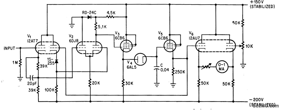
In this setup, the dual-triode amplifier (V2) serves to minimize the charging time constant of the voltmeter. This reduction is critical because it allows the voltmeter to respond more quickly to changes in voltage, thereby providing a more accurate representation of peak values. The amplifier's design contributes to a high input impedance, which prevents loading effects that could distort the measurement.
The circuit operates effectively within a voltage range of up to 40 volts, maintaining good linearity throughout this range. This characteristic is essential for applications where precise voltage measurements are required, such as in audio electronics or signal processing. The dual-triode configuration ensures that the amplifier can handle variations in input signals without significant distortion, thus preserving the integrity of the measured peak values.
Overall, the enhancement of the peak voltmeter's response through the addition of a dual-triode amplifier exemplifies a practical application of amplifier technology in improving measurement accuracy and speed in electronic instrumentation.Addition of dual-triode amplifier V2 to conventional peak voltmeter reduces charging time constant while increasing available time for measuring peak value. Linearity is good up to 40 v. -M. Uno, Amplifier Improves Peak Voltmeter Response, Electronics, 37:14, p 73. 🔗 External reference
Related Circuits

This is the circuit diagram of a USB-powered computer speaker, commonly referred to as multimedia speakers for PCs. The circuit features a single-chip design, operates on a low-voltage electrical power supply, is compatible with USB power from computers, includes...
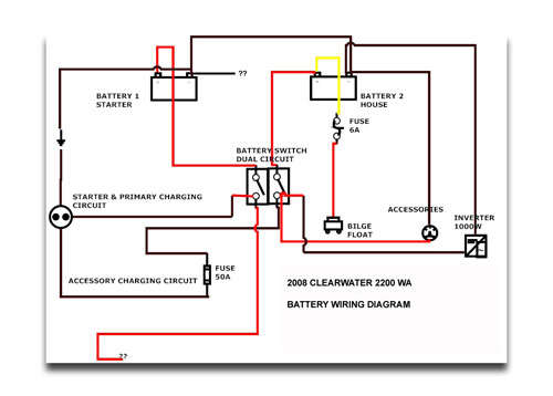
If the instruments have power when the key is turned on, the next step is to check the neutral safety switch. According to standard boat wiring colors, follow the yellow/red wire from the starter post on the key switch...
This circuit diagram illustrates the conversion of a speaker into a microphone. When sound waves impact the diaphragm of a speaker, fluctuations occur in the coil, generating an induced voltage. This induced voltage is typically substantial but low in...
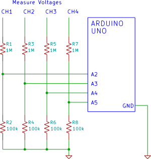
A four-channel voltmeter that displays voltage readings in a software application running on a computer. An Arduino reads the voltages and sends them to an application written in the Processing language. The described circuit comprises a four-channel voltmeter system that...
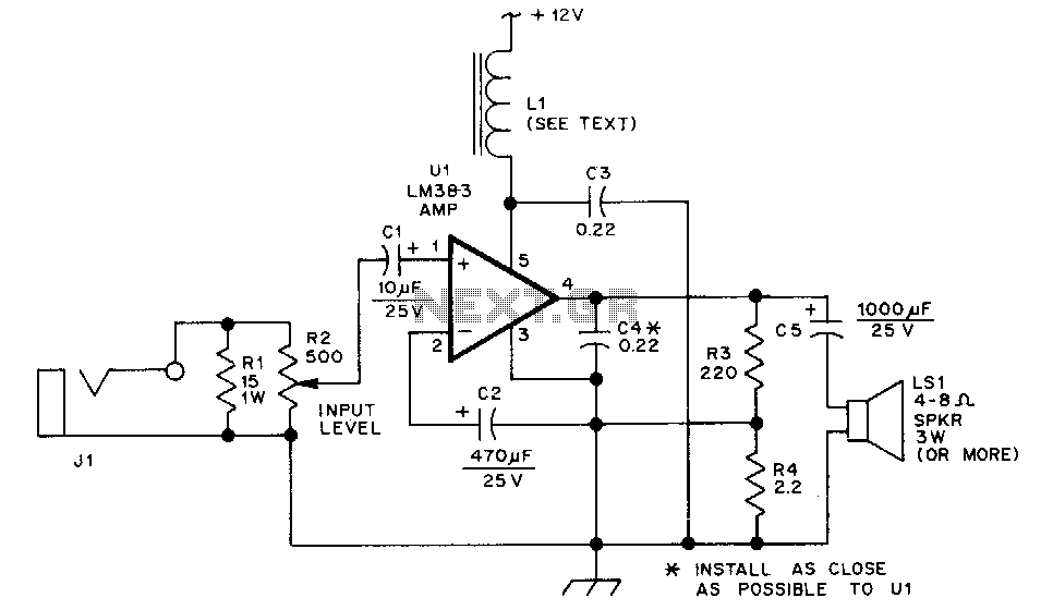
The LM383 is an audio power amplifier capable of delivering up to 8 watts of audio output. Resistor R1 serves as a load resistor for the audio output of a hand-held transceiver. Resistor R2 can be implemented using two...
A complete AM radio set based on the MK484 IC (formerly ZN414). It uses a PNP transistor and can drive a 150R loudspeaker. Chad has built a complete radio receiver using 1 IC and a single transistor. The IC...