
Stereo PC Speaker Powered USB Speaker Schematic Diagram
The USB-powered computer speaker circuit is designed to provide a compact and efficient audio amplification solution for personal computers. The TDA2822M IC is a robust choice for this application due to its ability to deliver substantial audio output while maintaining low power consumption. The implementation of a Zobel network using resistors and capacitors helps to stabilize the amplifier and improve the frequency response, minimizing potential distortion at higher frequencies.
The choice of a USB power source not only simplifies the power supply requirements but also enhances the portability of the speaker system, making it suitable for various applications, including portable audio setups. The inclusion of individual volume controls for each channel allows for precise audio management, catering to user preferences for sound balance.
When designing the PCB layout, it is crucial to ensure that the traces carrying audio signals are kept short and away from power supply traces to minimize noise interference. Additionally, proper heat dissipation measures should be taken into account, especially if the amplifier is expected to operate at higher volumes for extended periods. The use of a socket for the TDA2822M allows for easy replacement or upgrading of the IC, enhancing the longevity and versatility of the speaker system.
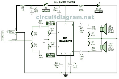
Overall, this circuit represents an effective solution for users seeking a simple yet high-performance multimedia speaker system powered directly from a USB port, making it ideal for use with laptops, desktops, and other USB-enabled devices.This is the circuit diagram of USB powered computer speaker, or it widely known as multimedia speakers for PCs. The circuit has single-chipbased design, low-voltage electrical power supply, compatibility with USB power from computer, simple heat-sinking, inexpensive, large flexibility and wide temperature tolerance.
At the heart of the circuit is IC TDA2822M. This IC is, actually, monolithic type in 8-lead mini DIP (Dual Inline Package). It`s designed for use as a dual audio power amplifier in battery powered sound players. Features of TDA2822M are very low quiescent current, low crossover distortion, DC source voltage down to 1. 8 volts and minimal output power of approximately 450 mW/channel with 4 ohm loudspeaker at 5V DC supply input.
An ideal power amplifier can be basically described as a circuit which can supply audio power into external loads without having producing substantial signal distortion and without having consuming extreme quiescent current. This circuit is powered by 5V DC source obtainable from the USB port of the Computer. When electrical power switch S1 is turned to on` position, 5V power supply is extended towards the circuit and power indicator red LED1 illuminates immediately.
Resistor R1 is actually a current surge limiter and capacitors C1 and C4 work as buffers. The operation of the circuit is very simple. Audio signals from the Computer audio port or headphone port are fed towards the amplifier circuit via R2 and C2 (for left channel), and R3 and C3 ( forright channel). Potensiometer VR1 used as the volume controller for left (L) channel, while potensiometer VR2 used to control the volume level of right (R) channel.
Pin 7 of TDA2822M receives the left channel sound signals and pin 6 receives the right channel signals by way of VR1 and VR2, correspondingly. Amplified signals for driving the left and right loudspeakers can be obtained at pins 1 and pin 3 of IC1, correspondingly.
Components R5 and C8, and R6 and C10 form the classic zobel network. Construct the circuit on a medium size, general purpose PCB and enclose inside a appropriate case. It really is recommended to utilize a socket for IC TDA2822M. The external connections ought to be made working with suitably screened wires for improved result. 🔗 External reference
Related Circuits
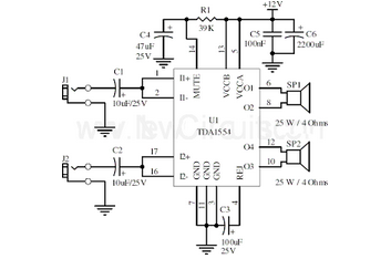
This document presents a 22-watt stereo audio power amplifier circuit diagram based on the TDA1554 integrated circuit from NXP Semiconductors (formerly Philips Semiconductors). The 22-watt stereo audio power amplifier circuit utilizing the TDA1554 IC is designed to deliver high-quality audio...
To alleviate any concerns related to high frequency, a ready-made Aurel audio FM transmitter module has been utilized. This compact circuit board, measuring 2 cm by 4 cm, supports a modulation frequency track and delivers an RF power of...
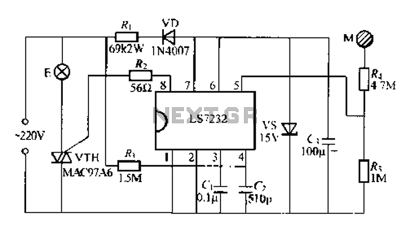
Figure (a) illustrates a general inverting amplifier circuit, which includes a 100k potentiometer as a feedback resistor connected in series between the input terminal and the inverting input to compensate for the DC bias current. The potentiometer (Rp) should...
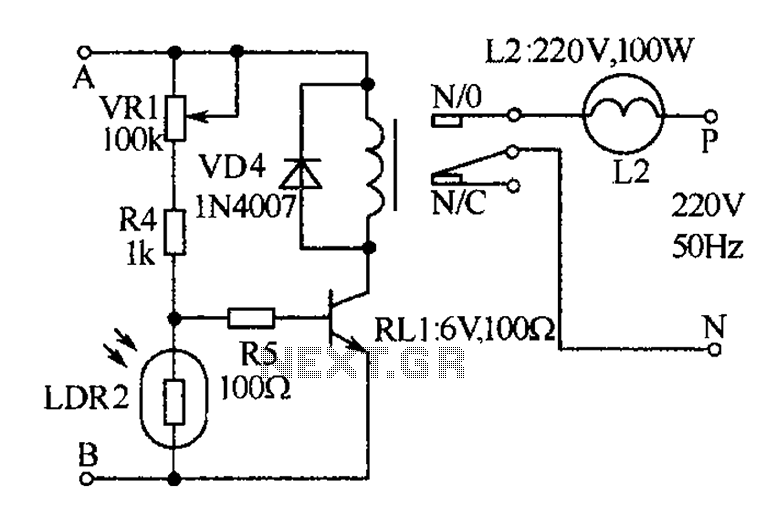
The receiver, as depicted in the figure, assists patients in avoiding missed audio signals during the daytime. The receiver operates independently, and the lighting will automatically turn off. At night, the lighting signal receiver activates simultaneously with the patient's...
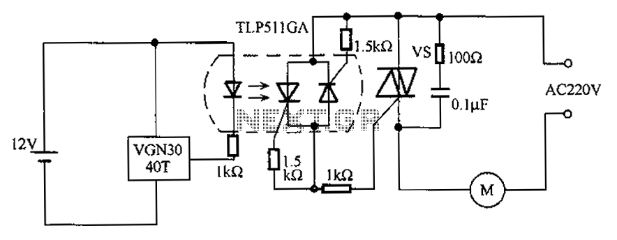
The circuit utilizes an integrated Hall effect sensor for an AC motor control system. It operates by detecting the presence of magnets or other magnetic objects near the Hall IC element of the induction motor. This configuration functions as...
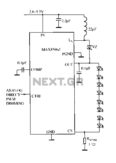
Driving a series of white LEDs allows for a consistent current to flow through each LED, resulting in uniform brightness. However, a disadvantage of this series configuration is that the driving voltage must account for the forward voltage drop...