
periodic timer

This timer circuit utilizes the 7555 timer IC, which is a versatile component commonly used in timing applications. The circuit operates in astable mode, allowing it to produce a continuous square wave output. The timing cycle is determined by the resistor and capacitor values in the timing chain. The 6-way rotary switch S3 allows the user to select different resistance values, thereby modifying the timing duration.
The timing chain consists of resistors R1 through R6, which can be adjusted to vary the output frequency. The output at pin 3 of the 7555 timer oscillates between high and low states, creating a pulse duration that can be calculated based on the formula for astable operation. The configuration ensures that the duty cycle remains balanced, providing a consistent on and off time.
The choice of a low leakage capacitor for C1 is critical, as it affects the timing accuracy. The use of electrolytic capacitors should be approached with caution due to their tolerance range, which can significantly impact timing. For applications requiring precise timing, the implementation of fixed resistors in combination with preset resistors is recommended, as well as sourcing components with a tolerance of 1% or better.
In practical applications, this timer circuit can be employed in various scenarios where a delay or timed action is required, such as in lighting systems, automated processes, or other electronic devices that necessitate a controlled timing mechanism. The ability to adjust timing through the rotary switch enhances flexibility, making this circuit suitable for a wide range of uses.This timer circuit is similar to the 5 to 30 minute timer except that when switch S1 is closed, the on/off actionof the circuit will continue indefinitely until S1 is opened again. A 7555 time and low leakage type capacitor for C1must be used. The 6 way rotary switch S3 adds extra resistance in series to the timing chain with each rotation, minimum
resistance point "a" maximum point "f". The 7555 is wired as an equal mark/space ratio oscillator, the timingresistor chain R1 to R6, being connected back to the output of the timer at pin 3. The output pulse duration is definedas:- This gives on and off times of about 379 seconds for postion "a" of S3 (just over 6 minutes), to about 38 minutes at point "f".
The times may of course be varied by altering R1 to R6 or C1. Below is my test circuit on my breadboard. The switch assembley is not present for clarity and a single 100k resistor and 33u capacitor (next to the 100nF ceramic) were used for test purposes. Please note that electrolytic capacitors have a tolerance of +/- 20%. This means that the nominal value can be higher or lower by 20%. For example, 33uF capacitor may be as high as 39. 6uF or as low as 26. 4uF. For precise timing periods, substitute a fixed resistor in series with a preset resistor, or buy high tolerance 1% capacitors and resistors.
🔗 External reference
Related Circuits
This device is designed for individuals seeking to achieve a tan while minimizing excessive exposure to sunlight. It utilizes electrolytic capacitors as one of its components. The tanning device operates by utilizing a controlled exposure mechanism that regulates the intensity...
The circuit diagram of this programmable sequencer can be utilized for various timing applications. An audible tone is generated before the start of each interval, while a seven-segment LED display indicates the current interval number. A buzzer sounds again...
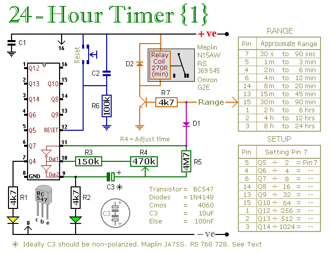
A pair of multi-range timers that provide timing periods extending up to 24 hours and beyond. Both timers are fundamentally identical, with the primary distinction being their relay behavior upon the completion of the timing cycle. Version 1 activates...

This is a simple smoke alarm circuit using a timer IC, the NE555. The circuit operates by illuminating a Light Dependent Resistor (LDR) with a lamp. When smoke obscures the light from the lamp, the resistance of the LDR...
Turns off your amplifier when idle for 15 minutes. Fed by amplifier tape-output. This circuit turns off an amplifier or any other device when a low-level audio signal fed to its input is absent for 15 minutes at least....
This is a lamp timer capable of operating two separate relay switches. Outputs can be in three (or restricted to two) states: OFF, delayed ON and constant ON. Delayed ON mode is indicated by the LEDs. The source code...