
Amplifier Timer
This circuit is designed to automatically turn off an amplifier or any connected device after a specified period of inactivity, specifically when no audio signal is detected for 15 minutes. The circuit is powered through the tape output of the amplifier, ensuring that it operates only when the amplifier is active.
The core of the circuit involves two operational amplifiers (IC2A and IC2B) that serve to amplify and square the low-level audio signal received at the input. This amplification is crucial for ensuring that even weak signals can be detected reliably. The output of these operational amplifiers is monitored by an LED (D4), which provides a visual indication of signal presence. When the LED is illuminated, it indicates that an audio signal is being processed, and this state is used to reset the timing mechanism of the circuit.
The timing function is managed by a timer IC (IC3), which begins counting when no audio signal is detected. The timer is designed to count for a duration of 15 minutes. During this period, pin 2 of IC3 remains low, which keeps two transistors (Q1 and Q2) in a conducting state. This allows current to flow through the relay, keeping it activated and thus maintaining power to the connected appliances through connector SK1.
If the audio signal is absent for the full 15-minute duration, IC3 will trigger pin 2 to go high, which turns off the transistors Q1 and Q2, subsequently deactivating the relay. This action completely cuts power to the connected devices, effectively turning them off and conserving energy.
Additional components such as capacitor C5 and resistor R9 may be utilized in the circuit to stabilize the operation of the timer and prevent false triggering due to noise or transient signals. The design ensures that the amplifier and any associated devices remain operational during active use but are automatically powered down during periods of inactivity, enhancing energy efficiency and prolonging the lifespan of the equipment.Turns-off your amplifier when idle for 15 minutes Fed by amplifier tape-output. This circuit turns-off an amplifier or any other device when a low level audio signal fed to its input is absent for 15 minutes at least. Pushing P1 the device is switched-on feeding any appliance connected to SK1. Input audio signal is boosted and squared by IC2A & IC2B and monitored by LED D4. When D4 illuminates, albeit for a very short peak, IC3 is reset and restarts its counting. Pin 2 of IC3 remains in the low state, the two transistors are on and the relay operates. When, after a 15 minutes delay, no signal appeared at the input, IC3 ends its counting and pin 2 goes high. Q1 & Q2 stop conducting and the relay switches-off. The device is thus completely off as also are the appliances connected to SK1. C5 & R9 🔗 External reference
Related Circuits
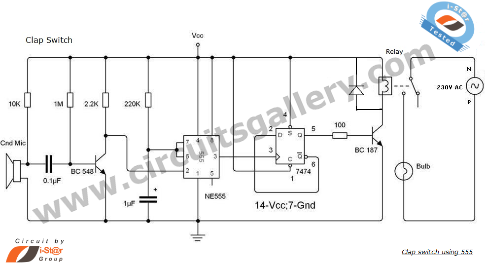
This is an intriguing 555 timer circuit designed to entertain and engage individuals while studying electronics in educational settings. Commonly referred to as a clap switch circuit, it operates as a sound-controlled flip-flop. This sound-controlled light can also function...
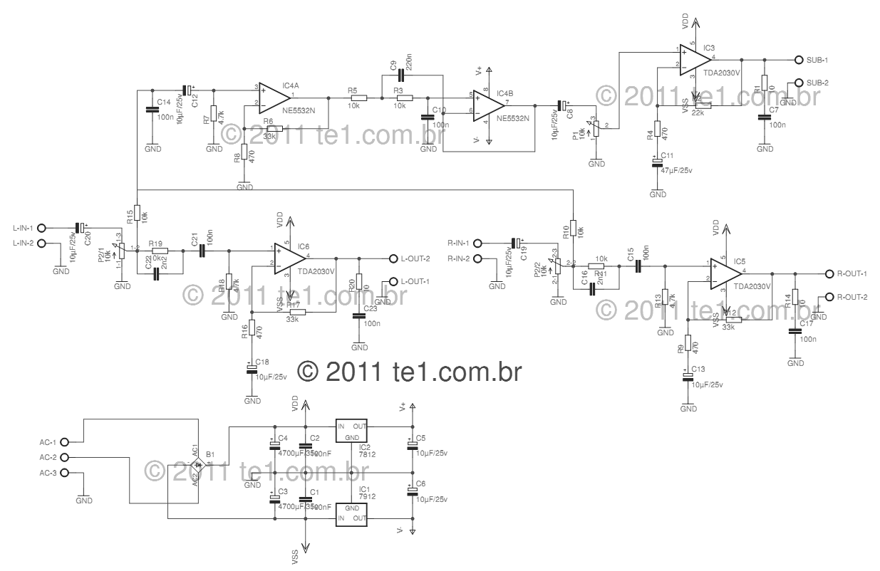
This circuit is a complete application for a 2.1 amplifier system, consisting of two satellite speakers powered by a TDA2030 and one subwoofer. This 2.1 system is commonly utilized in commercial applications as an amplifier for computers, enhancing audio...
A common collector amplifier circuit structure and its key components are outlined. The composition of the common collector amplifier circuit is fundamentally similar to that of a common emitter amplifier circuit, with two notable exceptions: one is the collector...
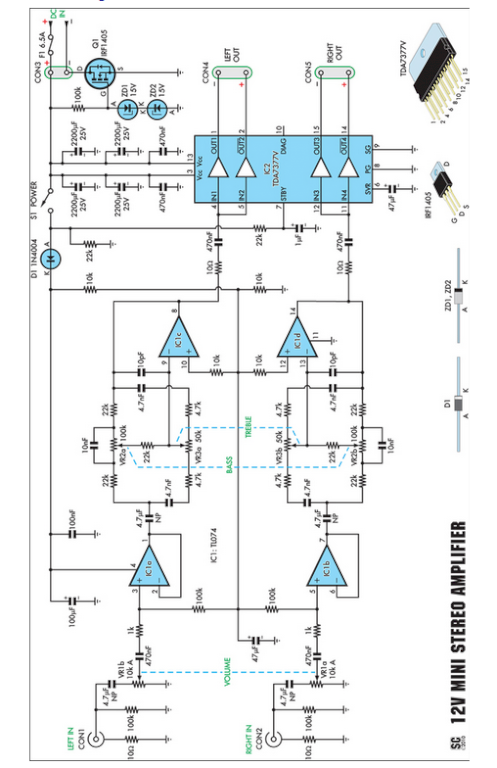
Amplifiers that operate on 12V DC typically do not deliver significant power and are often not classified as high-fidelity (hifi) devices. However, this compact stereo amplifier meets the power requirements effectively. This compact stereo amplifier is designed to operate efficiently...
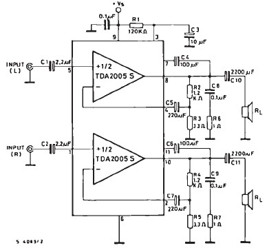
The TDA2005 car audio amplifier circuit is specifically designed for use in devices such as car radios, CD players, and similar equipment. This amplifier is based on the TDA2005 audio integrated circuit (IC), capable of delivering a maximum output...
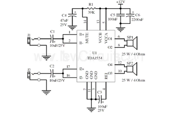
This document presents a 22-watt stereo audio power amplifier circuit diagram based on the TDA1554 integrated circuit from NXP Semiconductors (formerly Philips Semiconductors). The 22-watt stereo audio power amplifier circuit utilizing the TDA1554 IC is designed to deliver high-quality audio...