
Two Cmos Based 24-Hour Timers circuit
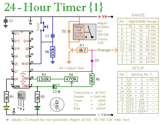
These multi-range timers are designed to accommodate a variety of applications where precise timing control is essential. Each timer can be set to run for durations ranging from seconds to 24 hours, making them versatile for both short-term and long-term timing requirements.
In Version 1, the relay is energized upon the completion of the set time, which can be particularly useful in applications where an action needs to be triggered at the end of the timing period, such as activating a motor or turning on a light. This configuration is advantageous for applications requiring immediate action upon timer expiration.
Conversely, Version 2's de-energizing relay upon time completion is suitable for applications where it is necessary to turn off devices or systems after a designated period. This design is particularly beneficial in energy-saving scenarios, as it minimizes power consumption once the timing cycle is completed.
Both versions utilize an efficient timing circuit that can be implemented using various electronic components such as resistors, capacitors, and a microcontroller or timer IC. The choice of components will depend on the desired accuracy and reliability of the timing function.
The power consumption characteristics of each version are crucial for applications where energy efficiency is a priority. Version 1's lower power usage during operation makes it ideal for applications where the timer is frequently active, while Version 2's reduced power consumption after the timer stops is more suitable for infrequent or intermittent use.
In summary, the selection between Version 1 and Version 2 should be guided by the specific functional requirements of the application, considering factors such as the need for relay activation or deactivation, energy efficiency during operation and post-operation, and the duration of the timing cycle required.A pair of multi-range timers offering periods of up to 24 hours and beyond. Both are essentially the same. The main difference is, that when the time runs out, Version 1 energizes the relay and Version 2 de-energizes it. The first uses less power while the timer is running; and the second uses less power after the timer stops.
Pick the one that best suits your application.. 🔗 External reference
Related Circuits

This schematic represents a radio receiver circuit based on the TDA7088T, which is suitable for use in mono portable and pocket radios. The TDA7088T is a bipolar integrated circuit designed to operate with a minimal number of peripheral components...
Configured with capacitive coupling by inserting a small capacitor between the phototransistor and the bipolar transistor, this relay circuit will respond only to rapid changes. This relay circuit utilizes capacitive coupling to enhance its responsiveness to fast signal changes. The...
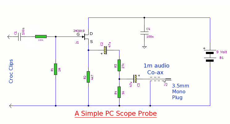
This simple PC scope probe functions as a FET follower, featuring high input impedance and low output impedance to match a microphone or line input socket on a PC or laptop. This design allows for practical examination of waveforms...
The 555 timer on the right is configured as an alarm sound generator, while the second 555 timer on the left operates as a 1 Hz astable multivibrator. The output from the left timer modulates the frequency of the...
This is a simple two-transistor lamp flasher circuit that can be used to flash a 6-volt lamp. The circuit is compact and can be easily fitted into a small enclosure. It utilizes two transistors: one is an NPN BC549,...
DTMF-based Robo Car design using the 8051 microcontroller project. This project demonstrates a method to control a domestic system using the DTMF tone generated by a telephone instrument when the user presses the keypad buttons of a mobile phone...
Warning: include(partials/cookie-banner.php): Failed to open stream: Permission denied in /var/www/html/nextgr/view-circuit.php on line 713
Warning: include(): Failed opening 'partials/cookie-banner.php' for inclusion (include_path='.:/usr/share/php') in /var/www/html/nextgr/view-circuit.php on line 713