
Personal Message Recorder Circuit
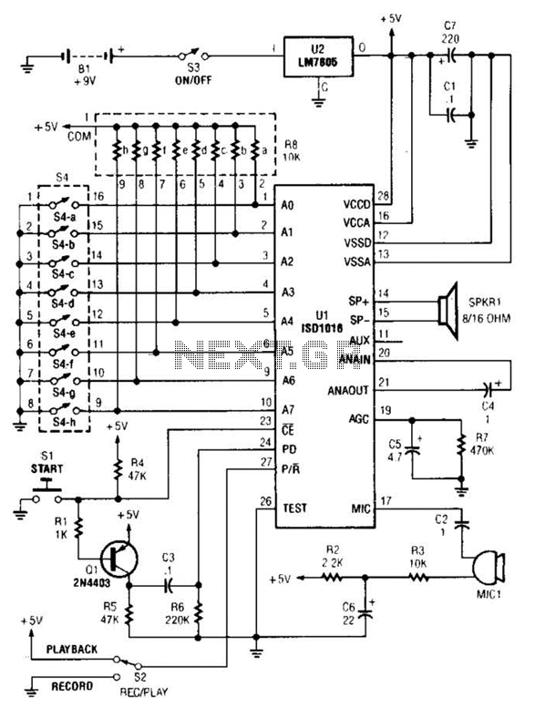
Eight external input lines allow the ISD1016's message space to be addressed in 160 equal segments, each lasting 100 milliseconds. When all address lines are held low, the storage array can accommodate a single, continuous 16-second message. Additionally, there is a special feature associated with the POWER DOWN input (pin 24) of U1. If the internal memory becomes full during recording, an overflow condition is triggered to activate the next device. After an overflow occurs, pin 24 must be set high and then low again before a new record or playback operation can commence. Transistor Q1, capacitor C3, resistor R5, and resistor R6 form a one-shot pulse generator that automatically clears any overflow condition each time the start switch (S1) is pressed. Switch S2 allows selection between playback and record modes. An 8-position DIP switch (S4) is included in the circuit to enable variation of the circuit's record/playback time from 0 to 16 seconds. The maximum available time occurs when all 8 switch positions are closed (set to the on position). A resistor network (R8) is implemented to provide a pull-up function for the address lines, thereby controlling U1's record/playback time.
The ISD1016 voice messaging system is designed to provide a straightforward and efficient means of recording and playing back audio messages. The preamplifier stage, which directly interfaces with an external microphone, is critical for capturing clear audio signals. The AGC feature ensures that variations in input signal levels do not adversely affect the recording quality, maintaining a consistent output level.
The functionality of the address lines is pivotal for segmenting the message storage, allowing for precise control over the recorded content. The ability to store messages in 100-millisecond segments provides flexibility for various applications, from simple voice reminders to more complex messaging systems.
The overflow condition management via the POWER DOWN input is a significant design consideration, ensuring that the system can handle memory limits gracefully, thus preventing data loss and facilitating seamless operation. The inclusion of a one-shot pulse generator ensures that the system can reset itself efficiently after an overflow, enhancing reliability.
The DIP switch configuration allows users to customize the recording duration, making the system adaptable to different user needs. The resistor network provides stability to the address lines, ensuring that the system operates correctly regardless of the selected recording time. Overall, the ISD1016-based personal message recorder presents a robust solution for voice messaging applications, combining simplicity with advanced functionality. The persona] message recorder is built around an ISD1016 CMOS voicc messaging system, which does away with the cumbersome and expensive analog-to-digital and digital-to-analog conversion circuits. A functional block diagram of the ISD1016 is shown. The ISD1016 contains all of the functions necessary for a complete message-storage system. The preamplifier stage accepts audio signals directly from an external microphone and routes the signals to the OUT (analog out) terminal.
An automatic-gain control (AGC) dynamically adjusts the preamplifier gain to extend the input signal range. Together, the preamp and AGC circuits provide a maximum gain of 24 dB. The internal clock samples the signal and, under the control of the address-decoding logic, writes the sampling to the analog-storage array.
Eight external input lines allow the ISD1016`s message space to be addressed in 160 equal segments, each with a 100-millisecond duration. When all address lines are held low, the storage array can hold a single, continuous, 16-second message.
However, there is a special addition to the POWER DOWN input (pin 24) of Ul. If the internal memory becomes full during recording, an overflow condition is generated in order to trigger the next device. Once an overflow occurs, pin 24 must be taken high and then low again before a new playback of record operation can be started.
Transistor Ql, C3, R5, and R6 form a one-shot pulse generator that automatically clears any overflow condition each time that start switch (SI) is pressed. Switch S2 selects cither the playback or the record mode. Switch S4an 8-position (a-h) DIP switchis included in the circuit to allow the circuit`s record/playback time to be varied from 0 to 16 seconds.
The maximum time available is when all 8 switch positions are closed (or set to the on position)..Resistor network R8 (a-h) is included in the circuit to provide a pull-up function for the address lines, which thereby controls Ul`s record/playback time. 🔗 External reference
Related Circuits
This circuit includes a Relay Timer Circuit. One of the most commonly used circuits is that of the 555 Timer integrated circuit (IC). The circuit is designed to control a relay based on a timing interval. The Relay Timer Circuit...
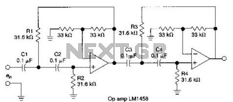
This circuit, which utilizes an LM1458 or a similar operational amplifier, functions as a fourth-order high-pass filter with a roll-off rate of 24 dB per octave. The resistor values Rx/R2 and RJRV can be adjusted to accommodate different cutoff...
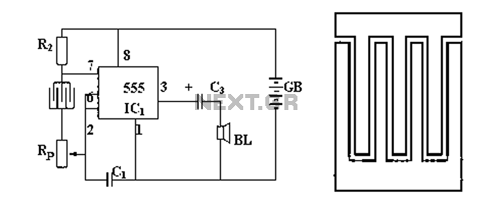
Figure 1 illustrates a circuit diagram related to an audio circuit that incorporates a resistance between two leads connected to a rain alarm probe. Figure 2 demonstrates the connection of a capacitor to the probe within the audio circuit....

All of ACC's repeater and remote base products support the control of synthesized remote base transceivers. One form of frequency control supported is compatible with transceivers using thumbwheel frequency selection. The controllers supply BCD (binary coded decimal) formatted data...
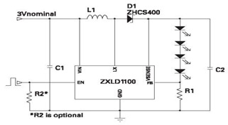
The ZXLD1100 is a PFM flyback DC to DC boost converter that operates in discontinuous mode. The following circuit diagram illustrates the configuration of four LED drivers for handset LCD backlighting using this device. The ZXLD1100 is designed to...
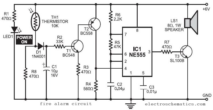
In this fire alarm circuit project, a thermistor functions as the heat sensor. When the temperature rises, its resistance decreases, and conversely, when the temperature falls, its resistance increases. Under normal conditions... In this fire alarm circuit, the thermistor is...