
Fire Alarm Circuit

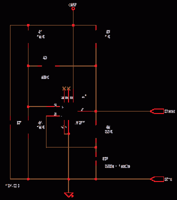
In this fire alarm circuit, the thermistor is a critical component that detects changes in temperature due to fire. The thermistor, typically a negative temperature coefficient (NTC) type, exhibits a decrease in resistance as the temperature increases. This property is essential for the circuit's ability to monitor environmental conditions effectively.
The circuit design includes a voltage divider configuration, where the thermistor is connected in series with a fixed resistor. As the temperature rises, the resistance of the thermistor drops, resulting in a change in voltage across the fixed resistor. This change can be monitored by a microcontroller or a comparator circuit, which can trigger an alarm or activate other safety measures when a predefined temperature threshold is exceeded.
Additionally, the circuit may incorporate an operational amplifier configured as a comparator to enhance sensitivity. The output of the comparator can drive an LED indicator or a relay to activate an external alarm system. Power supply considerations are also crucial, as the circuit must operate reliably under various conditions, ensuring that it remains functional during a fire event.
To improve the overall performance, it may be beneficial to include a calibration mechanism to account for variations in thermistor characteristics and environmental factors. Furthermore, the circuit can be designed with a delay feature to prevent false alarms caused by transient temperature spikes.
Overall, this fire alarm circuit utilizing a thermistor is a practical and effective solution for detecting heat increases associated with fire hazards, providing an essential safety mechanism in residential and commercial settings.In this fire alarm circuit project, a thermistor works as the heat sensor. When temperature increases, its resistance decreases, and vice versa. At normal.. 🔗 External reference
Related Circuits
This circuit functions as a simple analog-to-digital interface with a resolution capability of 10 to 12 bits. A 10-bit resolution translates to 1024 counts or divisions of a full scale (FS), which is approximately equivalent to 3.5 digits or...
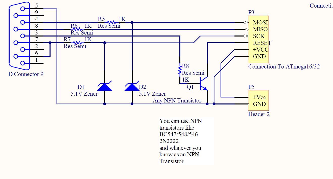
ISP programmer with circuit diagram for AVR Atmega32 microcontroller. This ISP burner circuit is an adaptation of the Pony programmer and uses PonyProg software. The ISP (In-System Programming) programmer designed for the AVR Atmega32 microcontroller facilitates the programming of the...
The TCM3105 FSK modem chip from Texas Instruments enables the construction of a modem compatible with Bell 202 or CCITT V23 standards. This modem circuit can transmit data at baud rates of 75, 150, 600, and 1200, and receive...

This project involves a simple 12V to 220V modified sine-wave inverter utilizing a 555 timer IC and a CD4017 decade counter. The inverter is capable of delivering 300W of continuous power and approximately 500W of maximum power output for...

The IR Jammer is a fun project that provides a bit of safe, non-destructive fun. The Infrared Remote Control Jammer allows you to render all IR remote controls inoperative! The microcontroller in this design allows for all 6 of...
This article demonstrates how to construct a custom version of the Fire-Stick infrared remote control system. The LITEON infrared receiver modules originally integrated into the Fire-Stick have been discontinued, necessitating a redesign of the original circuit boards. The core...