
Rain alarm schematic circuit diagram
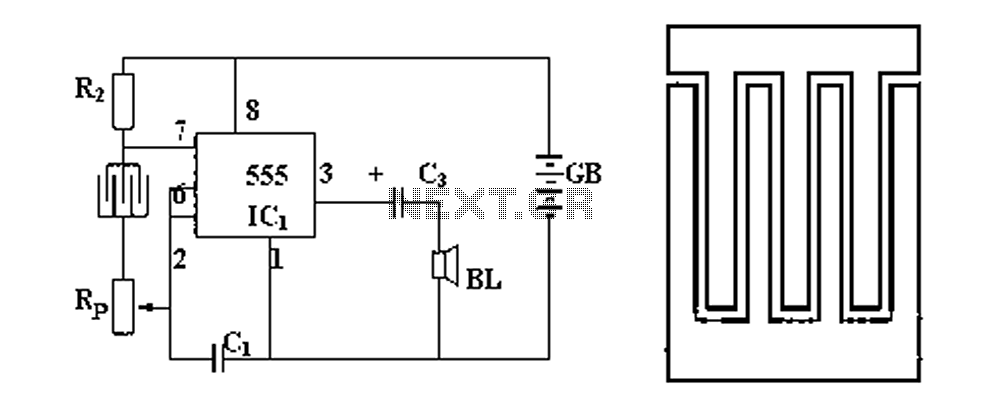
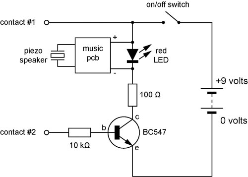
The described circuit functions as a rain detection and alarm system, utilizing a simple yet effective design. The primary components include a probe, which is sensitive to moisture, and a resistor that forms part of the detection mechanism. When raindrops fall on the probe, they create a conductive path between the two leads, effectively completing the circuit.
The audio circuit is designed to generate an audible alert when the probe detects moisture. This is achieved through the integration of a capacitor, as depicted in Figure 2, which may serve to filter or stabilize the signal generated by the probe. The capacitor allows for the proper functioning of the audio output, ensuring that the sound produced is clear and effective in alerting users to the presence of rain.
In addition to its primary function as a rain alarm, the circuit can be adapted for various applications requiring water detection. By modifying component values or configurations, the design can be tailored to suit different environments or sensitivity requirements. This flexibility makes it a valuable solution for diverse water alarm needs, ranging from outdoor rain detection to indoor flood monitoring. Overall, the circuit provides an efficient and reliable method for water detection and alarm signaling.FIG. 1 is a circuit diagram of it, it is in the audio circuit from the resistance between the two leads to a probe to rain alarm. Fig. 2 with CCL to make a probe connected to t he audio circuit, when the rain drops on the probe, the circuit is turned on, the sound will be issued. The alarm can also be used as a variety of water alarm device. Figure 1 Figure 2
Related Circuits
In its simplest form, a voice-over unit is just a microphone and change-over switch feeding an amplifier, the output from the microphone having priority over the amplifiers audio signal when the "push-to-talk" switch is pressed. In this circuit, a...
When light strikes the Light Dependent Resistor (LDR), its resistance decreases significantly. The voltage at the junction of the LDR and resistor R2 gradually charges capacitor C2 through resistor R1. After approximately 10 seconds, the voltage across the capacitor...
ATMega168 or ATMega328 microcontroller chip with Arduino bootloader (the one on your Arduino can be used temporarily) costs between $4.00 and $5.50. It is advisable to purchase an unbootloaded chip from Mouser for a lower price or a bootloaded...
A continuity tester is useful for verifying that there is a conductive path between two points. This circuit offers the advantage of being highly sensitive, providing both visual and audible indications of continuity. An audible tester is particularly beneficial...
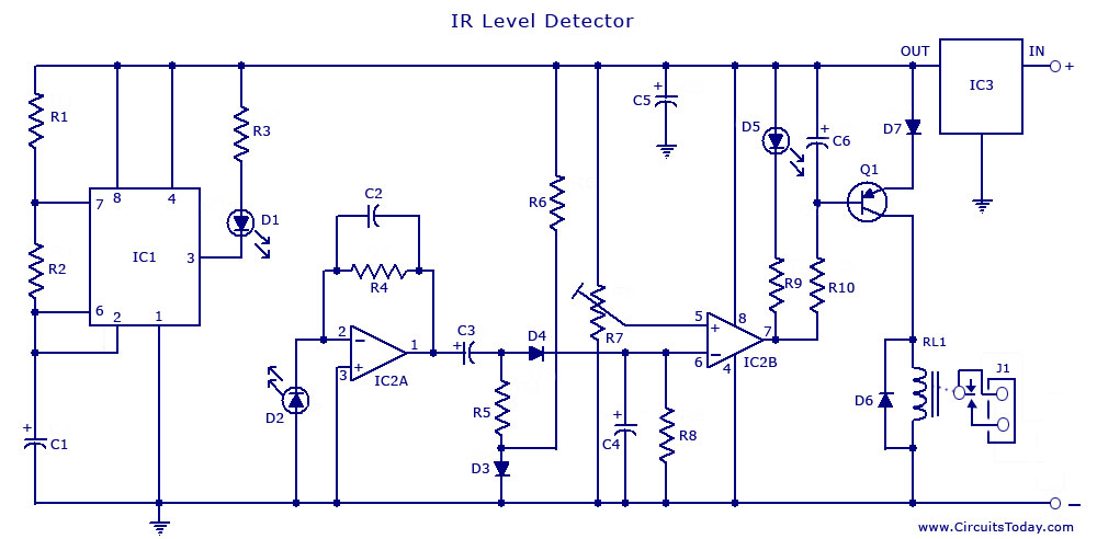
An infrared (IR) sensor or detector circuit diagram utilizing a 555 integrated circuit (IC), primarily employed as a water level or liquid level sensor and proximity detector circuit. The described circuit employs a 555 timer IC configured in a monostable...
The thermistor utilized has a resistance of 15k ohms at 25 degrees Celsius and 45k ohms at 0 degrees Celsius. A suitable bead-type thermistor can be sourced from the Maplin catalogue. The inclusion of a 100k potentiometer enables this...