
ph d scientist infrared sensor
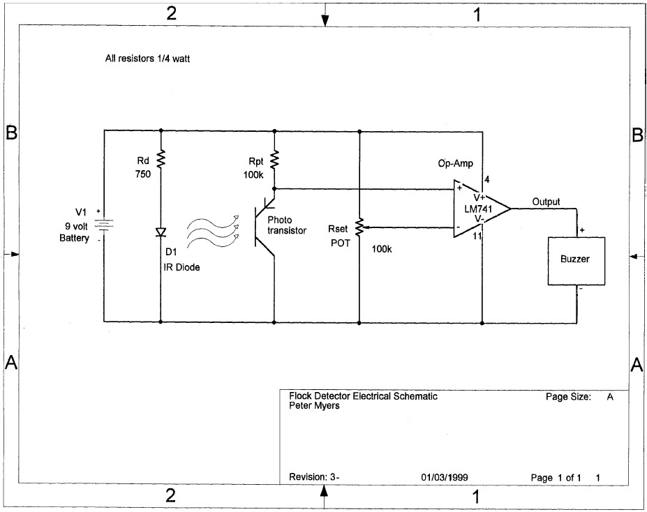
The electronic schematic for this device involves several key components and their interconnections. The infrared LED, operating at a specified forward current, is connected in series with a resistor (Rd) to limit the current and protect the LED from overcurrent conditions. The infrared phototransistor is positioned 2 cm away from the LED, forming a light path that the flocculent layer can interrupt. The phototransistor's output is connected to the non-inverting input of the 741 op-amp, which is configured as a voltage comparator. The inverting input of the op-amp is connected to a reference voltage set by a voltage divider, allowing the op-amp to trigger when the phototransistor output drops below this reference level.
The output of the op-amp drives a buzzer, which is connected in a way that it activates when the flocculent layer interrupts the infrared beam. The circuit is powered by a 9-volt battery, ensuring adequate supply for the LED, op-amp, and buzzer. To ensure the circuit's reliability in a wet environment, the components should be housed in a watertight casing, with only the LED and phototransistor heads exposed to the lake water, while the leads remain protected. This design allows for accurate depth measurement of the flocculent layer while safeguarding the electronic components from potential damage due to exposure to water. Proper soldering techniques should be employed for the op-amp and other components, ensuring secure connections and minimizing the risk of circuit failure.Build a device to determine the depth of the flocculent layer in a lake. The flocculent layer is a mud layer that has a similar consistency of water. It is pretty difficult to determine its depth accurately from the surface. I have a paper that describes a device able to measure it precisely from the surface and I think that I can build it, but there aren`t any part numbers. I need to order the right combination of parts. The idea is to use an infrared LED, which is placed 2-cm away from a IR photo transistor which is high when the light is blocked. The flocculent layer is sufficient to cut the beam. Once the beam is cut, the transistor is low and is connected to a 741 op-amp configured as a voltage detector, which triggers a buzzer (when the set point of the transistor is passed).
The reason infra red is used instead of a regular full light LED is that infrared is attenuated by water and thus, surface light does not interfere with the readings (at the floc layer depth, there is no ambient IR light). A 2-cm layer water does not cut the beam. A 2-cm layer of flocculent layer however cuts the beam of the IR LED. From the paper: "The infrared diode light source has a constant current supply (about 10 mA) determined by Rd.
The amplifier is a common 741 op-amp, available at any electronics parts store. Pin numbers for the op-amp are shown on the schematic;pins 1 and 5 are not used. The circuit board used in the assembly is a small perf-board, also available at any electronics parts store. The entire circuit operates on a 9-volt alkaline, transistor battery which should provide at least 24 h of continuous service.
The buzzer you have selected requires an oscillator to drive it. You want a buzzer such as the SMB-12L Star 12VDC Buzzer from Goldmine, which operates from a DC voltage You have selected a photodarlington transistor, whereas the schematic shows a phototransistor. A photodarlington has much higher gain and may not work properly in the circuit. You might try a G17146 from Goldmine. Or, since they are cheap, order both and see which works better. How are you going to keep the lakewater off the components but alow it to flow between the LED and photodiode The top of the diode and transistor can get wet, but the leads have to stay dry.
I`m not saying it can`t be done, there are many ways, I just thought it should be brought up. Good luck on your project. Since I need that setup to be built quickly, does radioshack carry all of the items I need I indeed intend to use the 2nd day shipping, which kind of kill the cheap prices. How are you going to keep the lakewater off the components but alow it to flow between the LED and photodiode The top of the diode and transistor can get wet, but the leads have to stay dry.
I`m not saying it can`t be done, there are many ways, I just thought it should be brought up. Good luck on your project. -> Everything but the head of the LED and of the photodiode will be exposed but sealed inside a watertight casing. The author of the paper did a good job desc. the the housing of the sensor. Pretty easy to buid. For the IR LED are they all the same I mean why the resistor and not mount it in direct I understand that the resistor is to limit the amount of current getting to the LED.
But does that mean that all the LED need the same current to function Now, for the soldering of the op-amp. How should I solder it I understand that I need to read more about the use of Op-amp. but it looks like I am running out of time. Rd and Rpt is just the nomenclature the designer decided on. Rd for the resistor in series with the diode and Rpt for the resistor in series with the photo transistor is what I`m guessing.
Rd is necessary to limit the amount of current that goes though the IR LED so it doesn`t burn out. Not all IR LEDs are the same They have different illumination outputs, forward voltage drops, angular widths, etc. It`s hard to s 🔗 External reference
Related Circuits
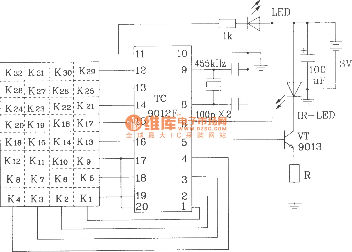
The TC9012 is a specialized off-screen remote control code transmitter. It incorporates an oscillator, divider timing generator, system code latch, data storage, key scan input, key scan output, and carrier control and output units. The internal 8-bit system code...
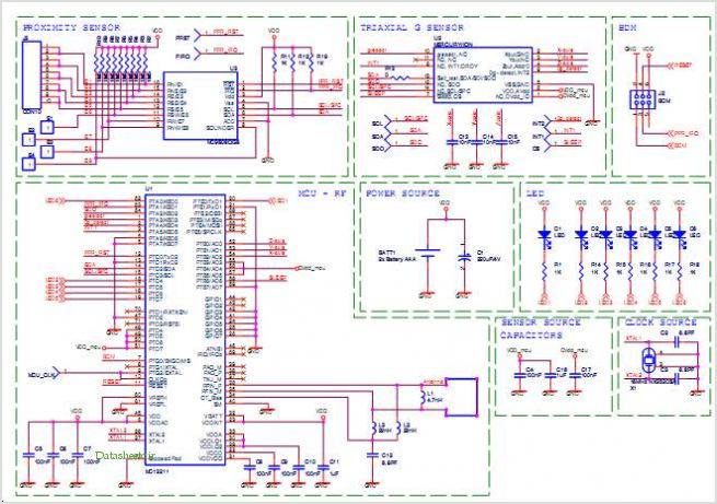
Many of today's high-performance FPGAs, microprocessors, DSPs, and industrial/embedded subsystems require sequencing of the input power PS10 and PS11. Historically, this has been achieved through: i) discrete methods using comparators, references, and RC circuits; ii) expensive programmable controllers; or...
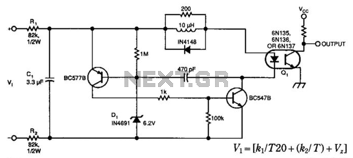
A simple voltage-controlled oscillator (VCO), coupled to instrumentation by an optoisolator, allows for the measurement of high voltages. The component values are suitable for a 0 to 600 V input range, with power dissipation in resistors RI and R2...
A light/dark sensing circuit is highly useful and versatile for various renewable energy projects, including automatic lighting and security systems. The article on Light Dependent Resistors (LDR) explains how an LDR can be employed in simple circuits to control...
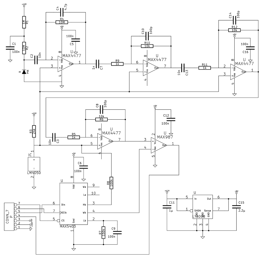
A noteworthy application note from Maxim detailed a gamma-photon detector utilizing a standard PIN diode as its sensing element. The circuit design appeared straightforward, prompting the decision to construct it, as having multiple measurement instruments is always beneficial. The gamma-photon...
The transmitter is shown and although straightforward, there are a couple of tricks that I had to incorporate to minimise battery drain during standby. Although the PIC quiescent current is only 200uA, that will still flatten a pair of...