
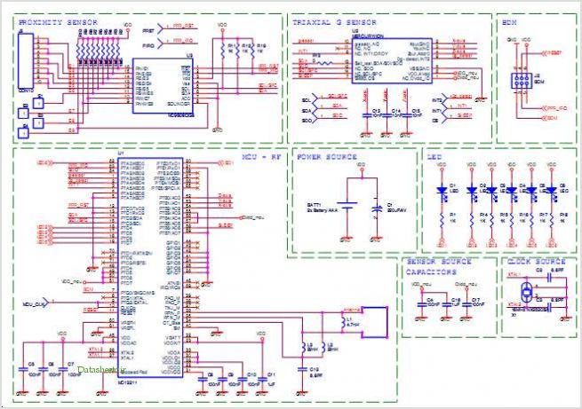
Proximity Sensor-based Remote Control Remote Control Demonstrator Board
The PS10 and PS11 integrated circuits are designed to facilitate power sequencing in complex electronic systems, ensuring that power is applied in a controlled manner to sensitive components. This is particularly critical in applications involving high-performance FPGAs and microprocessors, where improper power sequencing can lead to malfunction or damage. The integration of multiple functionalities into a single package minimizes board space and component count, contributing to a more compact and reliable design.
The programmable features of the PS10 and PS11 allow for customization according to specific application requirements. The programmable power-on reset interval (POR) is a crucial feature that can be adjusted using an external capacitor, providing flexibility in timing the power-up sequence. This is essential for ensuring that downstream components are powered on only after the supply voltage has stabilized, thus preventing erroneous operation.
The ability to daisy-chain multiple PS10 and PS11 devices enhances the scalability of the power sequencing solution. This feature allows for the sequencing of additional subsystems without the need for complex external circuitry, thus simplifying the design process. The immediate response of the power-good outputs to any deviations in input voltage further enhances system reliability, as it provides instant feedback for fault detection and system protection.
In summary, the PS10 and PS11 power sequencing devices represent a significant advancement in the design of power management solutions for high-performance electronic systems. Their integration of multiple supervisory functions, high-voltage operation, and programmable features makes them an ideal choice for modern applications requiring precise power sequencing.Many of todays high performance FPGAs Microproces- sors, DSP and industrial/embedded subsystems require sequencing of the input power PS10 PS11. Historically this has been accomplished: i) discretely using Comparators references & RC circuits; ii) using expensive programmable control- lers; or iii) with low voltage Sequencers requiring resistor d
rop downs and several high voltage Optocoupler or level shift components. The PS10 11 saves board space, improves accuracy, eliminates Optocouplers or level shifts and reduces overall component count by combining four Timers programmable input UV/OV supervisors, a programmable POR and four 90V open drain outputs. A high reliability, high voltage, junction isolated process allows the PS10 11 to be con- nected directly across the high voltage input rails.
The power-on-reset interval (POR) may be programmed by a capacitor on Cramp. To sequence additional sys- tems, PS10 11 may be daisy chained together. If at any time the input supply falls outside the UV/OV detector range the PWRGD outputs will immediately become IN- ACTIVE. Down sequencing may be accomplished with additional components (see page 11). By Supertex, Inc. 🔗 External reference
Related Circuits
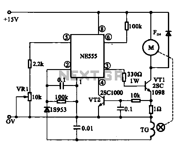
The Miniature DC Motor Speed Control circuit is designed to maintain a steady speed for micro motors, as illustrated in Figure 8-32. The circuit utilizes a voltage feedback mechanism suitable for applications such as tape recording machines that employ...
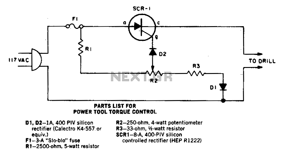
As the speed of an electric drill decreases due to loading, its torque also diminishes. A compensating speed control circuit restores power to the motor. When the drill slows down, the back voltage developed across the motor—connected in series...
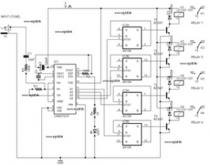
The following circuit illustrates a DTMF (Dual Tone Multi-Frequency) Remote Domestic System Control Circuit Diagram. Features: DTMF signals can be transmitted over a radio. The DTMF Remote Domestic System Control Circuit is designed to enable control of domestic appliances through...
This Project is used to indicate the temperature and it is also used as controller. The system will get the temperature from the IC and it will display the temperature over the seven segment display and this temperature was...
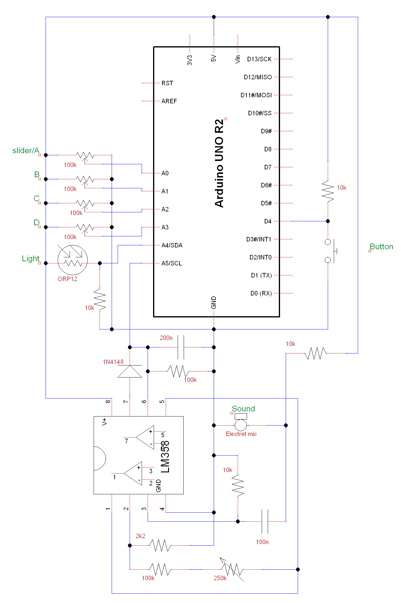
A circuit and Arduino code are designed to emulate a ScratchBoard approximately. The setup includes sound, light, a button, and four sliders, but it is not a direct replacement. It is important to change the COM ports in the...
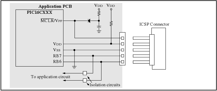
The programmer utilizes a serial signaling scheme to program the chip while it is in-circuit. The signaling is transmitted through the programming clock (PGC or ICSPCLK) and the programming data (PGD or ICSPDAT) pins. Additionally, the MCLR/VPP pin serves...