
Infrared Remote Control circuit
The presented circuit functions as a remote-controlled transmitter and receiver setup, designed primarily for controlling a motorized potentiometer within an audio preamplifier system. The transmitter employs a microcontroller (PIC) that operates at a quiescent current of 200 µA, which should be considered when powering the device with standard AA or AAA 1.5V batteries, as prolonged standby may lead to battery depletion.
The receiver circuit incorporates a motor drive system utilizing a full-bridge configuration formed by transistors Q1, Q2, Q4, and Q5. This arrangement allows for bidirectional control of the motorized potentiometer, enabling smooth operation in both forward and reverse directions. The design ensures that Q1 and Q2 cannot be activated simultaneously to prevent damaging short circuits across the power supply.
A relay is integrated into the receiver circuit to mute the preamplifier output during startup, with an automatic mute feature lasting for ten seconds. This relay is designed for a 5V coil, although alternative coil voltages may be accommodated with specific modifications, such as omitting diode D1 when a higher voltage relay is used. The relay contacts are connected directly to the output socket, ensuring no damage occurs to the preamp during operation.
Capacitor C6, which is a bipolar electrolytic capacitor, is specifically excluded from the PCB layout and should be mounted directly at the motor terminals to minimize interference from motor noise. The design allows for flexibility with capacitor selection, suggesting the use of a smaller ceramic capacitor if desired, while recommending adherence to the original specifications for optimal performance.
The receiver PCB dimensions are compact at 31mm x 64mm, facilitating integration into various preamp designs. However, care should be taken when selecting a motorized potentiometer to ensure compatibility with a 5V supply, as some may require higher voltages, which would necessitate additional modifications.
The system features a jumper (J1) that allows the user to enable or disable the power-on mute function, providing flexibility based on user preference. The mute relay can also be repurposed for other applications if desired, although the specifics of such modifications would depend on user requirements and interests.
Overall, this circuit represents a robust solution for remote control of audio components, with careful attention to power management and noise reduction, ensuring reliable and efficient operation.The transmitter is shown and although straightforward, there are a couple of tricks that I had to incorporate to minimise battery drain during standby. Although the PIC quiescent current is only 200uA, that will still flatten a pair of AA or AAA 1.5V cells over time.
The receiver provides motor drive (forward and reverse) for the motorised pot, and a relay for muting. The relay simply shorts out the preamp's output - this will not cause any damage to the preamp, as long as the relay contacts are connected directly to the output socket.
When the circuit is powered on, there is an automatic mute for 10 seconds, but this may be disabled if you don't want it. The board is designed to use a relay having a 5V coil, but other relay voltages can be used if desired - note that D1 must be omitted from the board if you use a higher voltage relay. The diode must be connected in parallel with the relay coil, but will have to be mounted off the PCB.
Make sure that you size the LED series resistor properly for the voltage you use - 2.2k as shown (with the 5V supply) will not give a bright glow, but this is intentional. You may wish to experiment to get the effect you want. To use a different relay voltage, simply disconnect the relay return from the 5V point, and connect to a suitable source voltage for the relay (remember to remove D1 from the board and mount it externally, in parallel with the relay coil.
Please note that C6 is not mounted on the PCB. This cap must be a bipolar (non-polarised) electrolytic, and it should be mounted directly to the motor terminals with the shortest possible leads to prevent motor noise from causing interference. You may use a smaller cap (100nF ceramic, for example), but to keep noise to the minimum I suggest the value shown.
Q1, Q2, Q4 and Q5 form a full-bridge motor drive circuit. When Q1 conducts, its collector will pull low, providing base current to Q5, which also turns on. This provides positive voltage on the M2 lead and negative on M1. Q2 and Q4 are switched on in the same way. The IC is programmed so that it cannot turn on Q1 and Q2 simultaneously, as this would cause a short across the supply, damaging the transistors. The complete receiver PCB includes the regulator (shown below), and measures 31mm x 64mm (approx 2.5" x 1.2").
This ensures that it can be made to fit into almost any preamp, although mounting the motorised pot may be a little more challenging if you don't have much space. While we are on the subject of the pot, make sure that you obtain one with a motor that will run at 5V - most will, but there may be some that need a higher voltage.
These are unsuitable for this circuit, although it is possible to use a higher voltage pot with a cut track and jumper wire. Details will be available if there is sufficient interest. Transmitter The only way you can really test the transmitter is to use the receiver, unless you have access to an oscilloscope.
Safety resistors cannot be used because the IR LED current is too high, so just make sure that you don't make a mistake. The IC will not tolerate reverse polarity or having the supply connected to the wrong pins, so be very careful to ensure it is inserted correctly.
Receiver Connect the receiver to a suitable power supply - remember that the supply earth (ground) must be connected! When powering up for the first time, double check that all wiring is correct - there is no room for errors!
If you have made a mistake in the wiring there is a very strong possibility that something will be damaged. When power is applied, the mute relay should remain de-energised for 10 seconds, and should operate after the timeout.
Test that the transmitter operates the mute relay (one press of the button to mute, the next to unmute) and the motor drive for the pot. If the pot turns in the wrong direction, simply reverse the wires to the motor. The jumper (J1) allows you to select or de-select Power-on Mute (PoM). When the jumper is in the position shown, PoM is enabled and the circuit will automatically mute for 10 seconds at power-up.
Place the jumper is the other position to disable the auto-muting (remote mute is not affected, and works with the jumper in either position). Naturally, if you want to use the mute relay (or mute pulse) for some other purpose you may do so (although I'm unsure what other possibilities there may be that would actually be useful).
Note that the mute switching is currently toggled between states with alternate presses of the button on the remote transmitter. Again, if there is sufficient interest in using the mute output for something else, I shall offer an alternately programmed PIC that outputs a single pulse for each button press.
🔗 External reference
Related Circuits
The following diagram is the circuit diagram of a 20W power amplifier built using the tube component EL34. The EL34 is a well-known tube, ideal for power tube amplifiers. The circuit presented is a complete design that includes both...
The sensors used are silicon phototransistors and Cadmium Sulfide (CdS) photocells. Both of these sensors allow less current to flow when they are dark than when lighted. Phototransistors change their conductance while photocells change their resistance depending on the...
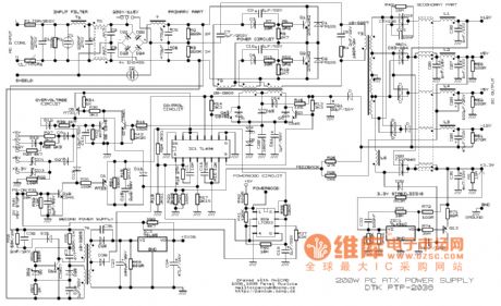
This example presents a switch DC regulated power supply circuit designed for buck-mode +5V applications. It consists of a power supply circuit, an impulsator, a voltage sampling or pulse width modulation circuit, and a buffering driver circuit, as illustrated...
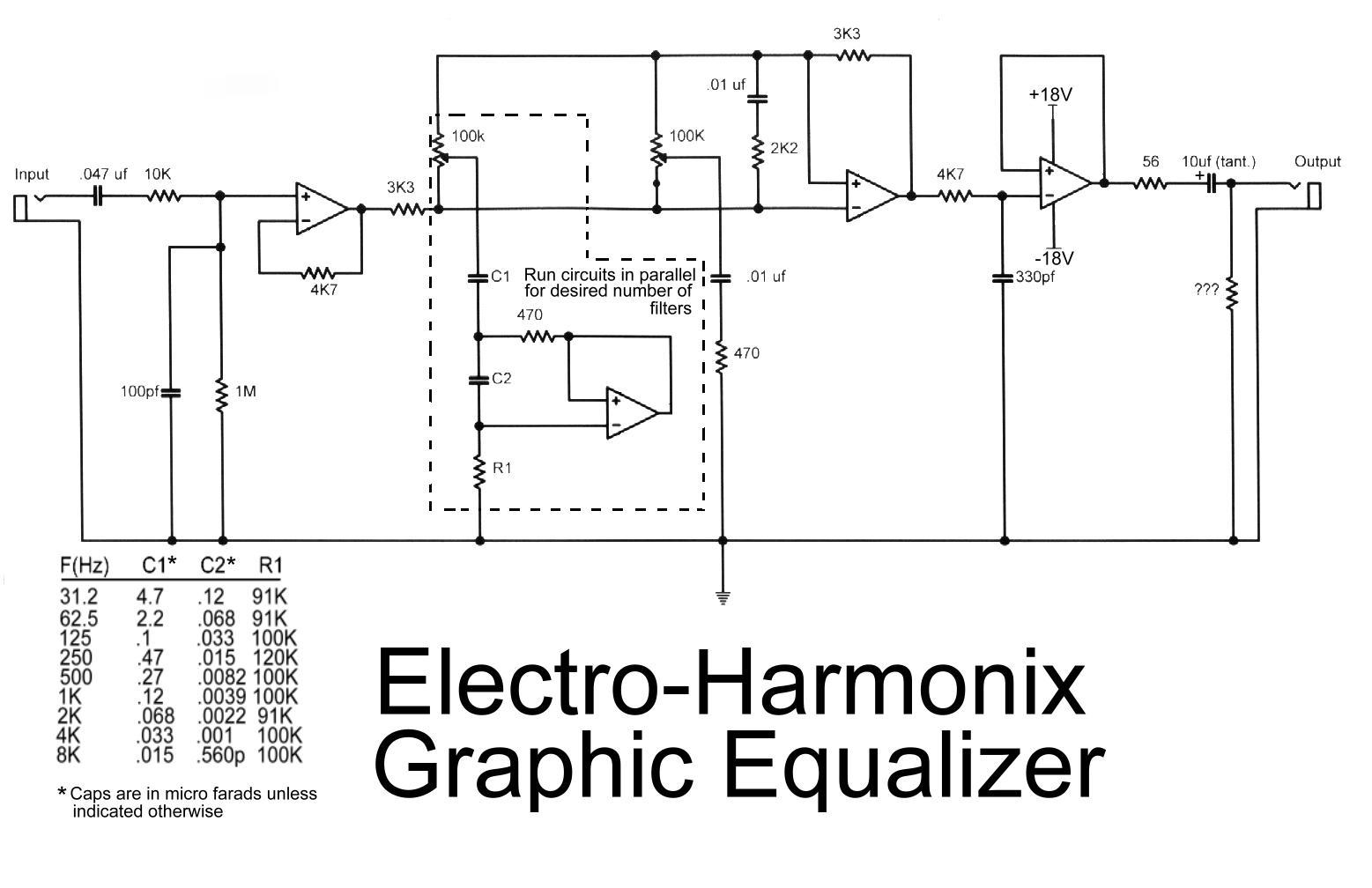
This is the diagram of the Electro-Harmonix graphic equalizer. The number of channels can be specified according to requirements by paralleling the components: C1, C2, R1, an operational amplifier, potentiometer, and a 470-ohm resistor. The frequency to be boosted...
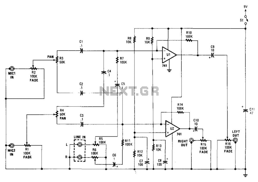
This stereo mixer features two mono mixers and a modification to the microphone inputs. When a microphone is in use, its output is directed to the microphone input of the circuit. The signal is then processed through resistors R1...
The circuit consists of an infrared transmitter-receiver pair that uses infrared beam transmission to switch the toy car on or off. It can be modified to allow the toy car to turn left or right. To operate the toy...