
Phantom and T powering for condenser microphones

The RF condenser microphone circuit operates on a 12V power supply, which is transmitted through a phantom power configuration. This design allows for the microphone to receive power and audio signals simultaneously over the same cable, minimizing the need for additional wiring and ensuring a cleaner audio signal. The phantom power circuit typically utilizes an XLR connector, where pins 2 and 3 carry the positive voltage and the audio signal, while pin 1 is grounded and serves as a shield against electromagnetic interference.
In the context of the Fet-80 series microphones, the integration of solid-state technology allowed for greater reliability and reduced maintenance compared to their vacuum tube predecessors. The introduction of phantom power by Neumann represented a significant advancement in microphone technology, enabling longer cable runs without the degradation of audio quality. The standardization of the phantom power voltage at 48V has become a widely accepted practice in the industry, allowing for compatibility across various microphone brands and models.
The T-System, an earlier method for powering condenser microphones, operates differently by applying power across pins 2 and 3 while using pin 1 solely for shielding. This system, while effective, lacks the compatibility and convenience offered by phantom power, which has become the preferred method for professional audio applications. The evolution of microphone powering methods reflects the ongoing advancements in audio technology and the industry's push towards more efficient and effective solutions.An RF condenser design, it was powered by 12v, supplied to the microphone via the mike cable using a phantom circuit. This is the first known usage of a phantom circuit for microphone powering[1]. Sometime around 1970, Neumann introduced the Fet-80 series of condenser microphones that were solid state and remotely powered via the microphone cable.
In typical German fashion, they decreed that these microphones were the be-all and end-all to microphones of any sort, and they promptly discontinued all of their vacuum tube microphones. Of course, nearly 40 years later, we know different, with the venerable U47 now selling for the price of a car.
Here then, are a series of articles, that explain this important concept and how it works. BTW, Neumann "gave" the idea to the industry; they claim that they trademarked the term, phantom power, and gave the concept and the term to our industry. There! Something for free from Neumann! (But as you can see, Schoeps beat them to the punch, however it was Neumann who standardized the value at 48V.
) About that time (1965), another (non-compatible) system for powering condenser microphones via the microphone cable was in use. This system is known as T-System, A-B Powering or Modulation Lead Powering. Phantom powering uses pins 2 and 3 of the XLR for the postitive side of the power supply, and pin 1 of the XLR for the negative side of the supply.
T-powering puts the power source across pins 2 and 3, with pin 1 only serving as the shield conductor. 🔗 External reference
Related Circuits
This circuit consists of a single transistor functioning as an amplifier, providing significant amplification for weak and unipolar signals, which can then be fed into a more powerful amplifier. The described circuit utilizes a single transistor in a common-emitter...
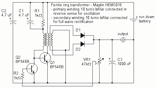
How to create a Joule Thief circuit to power a clock, including circuit details and tips for construction. The Joule Thief circuit is a simple and efficient boost converter that allows the extraction of usable voltage from low-voltage sources, such...
Many antique radios operate on batteries, including tube portables like the Zenith model K-401 and "farm" radios used in rural areas without electrical power. This article provides historical context on battery usage in early radios and offers guidance on...
The compact, low-cost condenser microphone audio amplifier described here provides high-quality audio output of 0.5 watts at 4.5 volts. It can be utilized in intercom systems, walkie-talkies, low-power transmitters, and packet radio receivers. Transistors T1 and T2 constitute the...
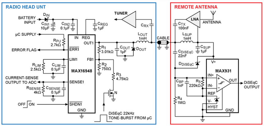
A design for a phantom antenna power-supply system compatible with the Digital Satellite Equipment Control (DiSEqC) communication standard, utilizing the MAX16948 automotive dual, high-voltage LDO/switch. The application circuit provides a remote antenna power supply and enables one-way communication from...
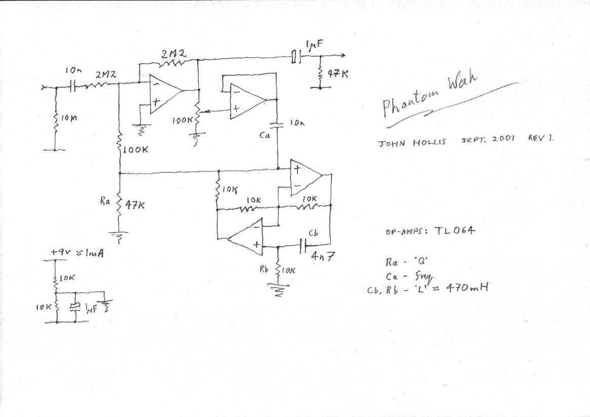
This is an op-amp implementation of a Vox style wah, with the inductor replaced by a gyrator circuit. With the component values given the frequency response is similar to a standard wah. By replacing one of the resistors with...