
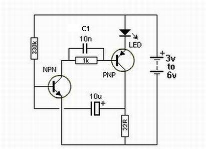
Joule thief circuit powering a clock
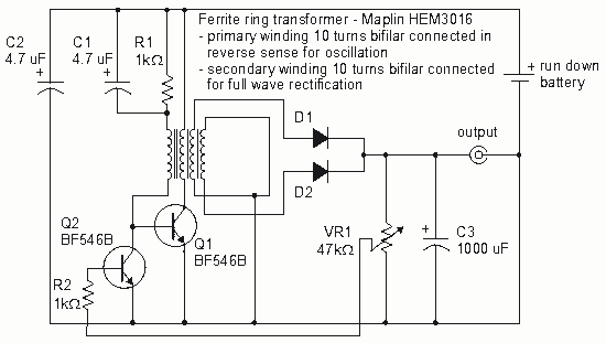
The Joule Thief circuit is a simple and efficient boost converter that allows the extraction of usable voltage from low-voltage sources, such as depleted batteries. This circuit is particularly useful for powering devices like clocks that require a minimal amount of current.
To construct a Joule Thief circuit for powering a clock, the following components are typically required:
1. **Transistor (e.g., 2N3904 or BC547)**: This acts as the primary switching element, allowing the circuit to boost the voltage.
2. **Inductor (e.g., 100 µH)**: A ferrite core inductor is commonly used, which plays a crucial role in energy storage and voltage boosting.
3. **Resistor (e.g., 1 kΩ)**: This resistor is used to limit the base current to the transistor.
4. **Diode (e.g., 1N4148)**: A fast-switching diode is necessary to rectify the output voltage and prevent backflow of current.
5. **Capacitor (optional)**: A small capacitor can be added at the output to stabilize the voltage.
The circuit operates by charging the inductor when the transistor is in the "on" state. Once the transistor switches off, the magnetic field in the inductor collapses, inducing a higher voltage across the inductor. This boosted voltage can then be rectified by the diode and used to power the clock.
For optimal performance, it is advised to ensure that the inductor is properly wound with the appropriate number of turns (typically around 30-40 turns of enamel-coated copper wire around a ferrite core). The circuit should be tested with different values of resistors to find the best base current for the transistor, ensuring efficient switching and minimal power loss.
When integrating this circuit with a clock, it is essential to verify that the output voltage meets the clock's requirements, usually around 1.5V to 3V. This can be achieved by adjusting the number of turns on the inductor or modifying the resistor values.
Overall, the Joule Thief circuit is an excellent solution for extending the life of low-voltage batteries while providing a reliable power source for low-power devices like clocks. Proper assembly and component selection are crucial for achieving optimal functionality.How to make a joule thief circuit power a clock. The circuit and Tips for making it. 🔗 External reference
Related Circuits
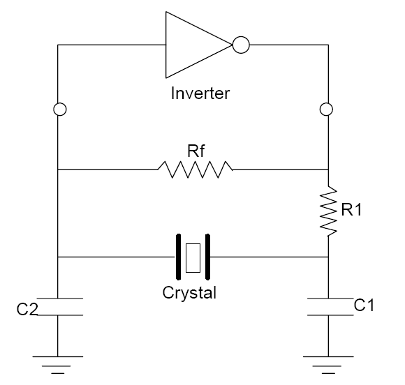
Oscillation is expected at the resonant frequency where the positive feedback is in phase with the input, specifically at 0 degrees. For oscillation to take place, the gain must be equal to or greater than 1 at that frequency....
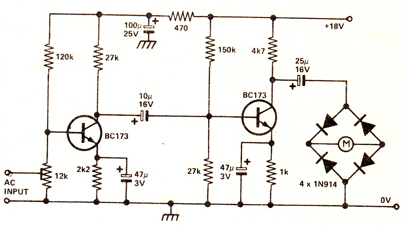
The circuit illustrates a two-stage voltage amplifier that drives a recording level meter. An AC signal input is amplified and rectified, with the resulting DC voltage displayed on the meter. This circuit is compatible with tape recorders or audio...

The pressure transmitter circuit data acquisition system utilizes the 1B31, an 18-bit A/D converter (AD1170), and an MCS-51 microcontroller. The configuration, as depicted in the accompanying diagram, features a full-scale output voltage of 10 mV from the pressure transmitter...
A small delay circuit is required to produce a pulse for a cell phone vibrational motor every 0.75 seconds, with an adjustable delay time ranging from 4 to 10 seconds. The circuit will be powered by a 9-volt battery. To...
This circuit design features a modular arrangement that enables users to select only the modules best suited to their needs, allowing for the construction of a chain ranging from one to five modules in length. For those seeking a...

A biaxial magnetic field sensor application circuit is illustrated in the figure. This circuit utilizes a biaxial magnetic sensor HMC1002 along with two AMP04 operational amplifiers (A1, A2) to measure the magnetic field in both the X-axis and Y-axis...