
Phase sequence detector
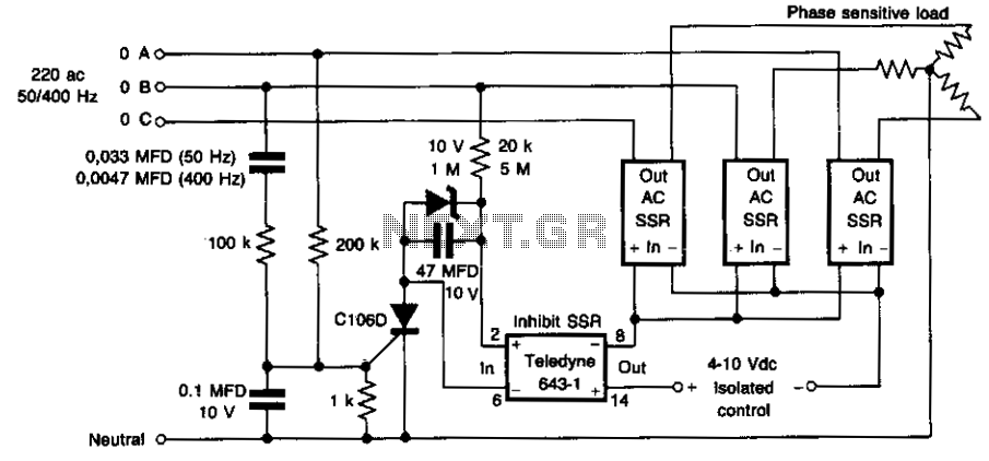
The circuit utilizes three power solid-state relays (SSRs) to control the load based on the phase relationship between phase A and phase B. The primary function of this circuit is to prevent potential damage to the load that could occur due to incorrect phasing, which is a critical concern in three-phase systems.
In normal operation, when phase A leads phase B, the SSRs are activated, allowing current to flow to the load. This leads to the desired operation of the connected equipment. However, if the phase sequence is incorrect, specifically if phase A lags phase B, a cancellation effect occurs in the input currents. This cancellation prevents the necessary triggering of the silicon-controlled rectifier (SCR) and the inhibit SSR, which effectively isolates the load from the power source, thereby protecting it from damage.
The inclusion of the inhibit SSR is essential for maintaining electrical isolation at the input. This SSR serves as a safety mechanism, ensuring that under conditions of incorrect phasing, the circuit remains inactive, preventing any unintended operation of the load. The design of this circuit emphasizes reliability and safety, making it suitable for applications where phase integrity is critical.
Overall, the circuit provides a robust solution for managing phase relationships in three-phase systems, ensuring that loads are only energized under correct phasing conditions, thus enhancing the longevity and reliability of the connected equipment.This circuit prevents damage to the load due to incorrect phasing. The three power SSR's are only permitted to turn-on for a phase sequence of phase A leading phase B. If phase A lags phase the input currents will cancel, causing the SCR and the inhibit SSR to remain off until the sequence is reversed. The inhibit SSR is included to maintain isolation at the input. 🔗 External reference
Related Circuits

An embedded C-based RF-controlled robot equipped with a metal detector, along with wireless image and voice transmission capabilities. This project report is intended for electronics and communication engineering students. The project involves the design and implementation of an RF-controlled robot...

The DIAC is a 28V bidirectional trigger device commonly used in inexpensive phase control applications. Its trigger voltage is relatively high for 115VAC phase control. In the past, a similar low voltage trigger device known as a Shockley diode...

This design has not been referred to as a GOLD detector, as that term is reserved for more complex devices capable of distinguishing gold from other metals. There is a significant difference between detecting gold and ordinary metals, known...
The TEM, specifically the Jeol 2000fx model, is equipped with two additional detectors: a secondary electron detector for SEM imaging and a STEM detector located at the bottom of the microscope. As the system dates back to the 1980s,...

The presented schematic illustrates the construction of a simple PIR motion detector sensor. PIR sensors are capable of detecting motion and are primarily utilized to determine if a person has entered or exited the sensor's range. These sensors are...

This circuit responds to RF signals below the standard broadcast band up to over 500 MHz and provides both visual and audible indications when an RF signal is detected. By adjusting the bias of diode D2 with the R2...