
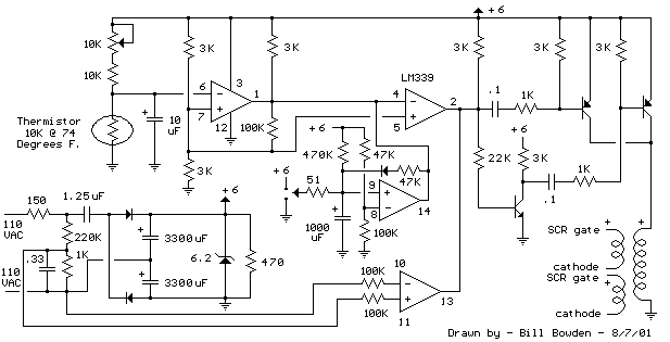
SCR Phase Control Speed Control/Dimmer
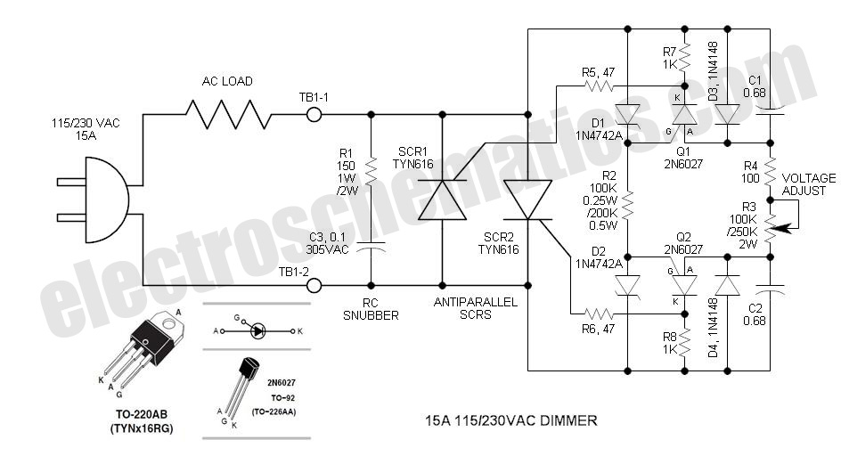
The DIAC and PUT circuits discussed are integral to various phase control applications, particularly in dimmers and motor speed controllers. The DIAC serves as a reliable trigger mechanism, allowing for the precise control of AC voltage. The use of a single potentiometer to control both halves of the AC cycle through anti-parallel SCRs enhances the circuit's efficiency and user-friendliness, ensuring consistent performance across different load conditions.
In designing these circuits, careful attention to component selection is crucial. The matching of zeners and capacitors not only ensures balanced operation but also enhances the stability and reliability of the circuit. The choice of a polypropylene capacitor over polyester is particularly important in high-voltage applications, where reliability is paramount. Furthermore, the implementation of a snubber circuit is essential for protecting sensitive components from voltage spikes and transients, which can result from the rapid switching actions inherent in AC circuits.
Overall, the combination of DIAC, PUT, and SCR technologies provides a robust framework for controlling AC power in a variety of applications, offering advantages in thermal management, reliability, and operational efficiency. The design considerations outlined here are vital for engineers looking to implement effective phase control solutions.The DIAC is a 28V bidirectional (bilateral) trigger device that is used on virtually all inexpensive phase controls. The trigger voltage is somewhat high for phase control of 115VAC. Years ago, there was a similar low voltage (6 to 8V) trigger device called a Shockley diode. Unfortunately, these never caught on and today are EXTINCT. The 2N6027 Pr ogrammable Unijunction Transistor (PUT) can perform a similar function, but is polarity sensitive so it does not lend itself to TRIAC control. However, if two such PUT trigger circuits are employed for anti-parallel SCRs, some interesting things are apparent.
Most important is the ability to control both trigger circuits with a single potentiometer so that both half-cycles are controlled identically. To obtain best balance, the zeners and capacitors must be matched. Both zeners and capacitors are specified for a tolerance of 5%, but I selected mine for better than 1% with my DMM.
Purchase a few additional components so that you may obtain a good match. PUT operation is simple. Its threshold voltage is programmable so that it can trigger at low voltages. In this circuit it is set via the 12V zeners. When the PUT anode voltage exceeds the gate voltage by one junction drop, the PUT fires and dumps the timing capacitor into the SCR gate circuit. It resets when the AC line voltage reverses. I made a PUT relaxation oscillator flasher circuit that you may wish to experiment with: The typical DIAC controlled TRIAC dimmer tends to snap-on at the minimum voltage when the adjustment is slowly increased.
After snap-on, the voltage may be reduced if desired. The snap-on phenomenon is caused by the lagging phase relationship of the AC voltage signal that appears across the timing capacitor before the DIAC threshold is reached. After it initially fires, the timing starts at line voltage zero crossing. The timing circuit in this control completely avoids this problem by resetting the capacitor voltage each half-cycle via reverse diodes across the two timing capacitors.
Thermally, there are numerous advantages. Splitting the output current in half reduces the device current significantly and provides a much lower thermal resistance to the ambient. Also, SCRs are rated for a maximum Tj of 125 °, while TRIACs may be limited to only 110 °C. Then, of course, SCRs are available in current ratings extending to hundreds of amps ” well over ten times that of the largest TRIACs.
SCRs are simply more rugged. First it provides a circuit to absorb reactive energy when either SCR recovers (stops conducting current). As you may know, a rectifier conducts current in the reverse direction for a short period of time (e.
g. 5 µS) when it becomes reversed biased. The flow of this current stops abruptly and any series circuit inductance then causes the generation of a transient voltage (spike). The snubber is a place for this current to go so it cannot develop a high voltage. Second, it provides a resistive load for high frequency line noise and transients. Such noise or transients can potentially cause an SCR to turn on for a half-cycle. One common source of transients is simply the power switch when it closes. Film resistors are not robust in handling voltage transients so I specified a ceramic composition resistor.
Polyester capacitors have poor reliability at 230VAC, so I specified a polypropylene capacitor that is AC rated. In my circuit, I used a Quencharc device that contains both resistor and capacitor ” it is AC rated for 125VAC.
The load voltage is easy to see here as it increases in phase. The base line is rather indistinct due to the low power load used (7. 5W lamp) ” the snubber reactance causes significant voltage drop across the lamp. The gate current indicates a peak current of about 200mA and a time constant of about 32 µS ” essentially 47 © * 0. 68 µf. The leading edge spike is caused by the inductance of the 1 © shunt resistor used. Th 🔗 External reference
Related Circuits
The first pulse motor that is used to position control. Features were incorporated for positioning control. This does not mean intelligent and autonomous driving the motor in response to movement commands from the host. The key to controlling the...
Despite the high impedance of its inputs, the Darlington transistor Q10 generates sufficient current to drive an LED. The inverted output of Q10 powers the internal LED of opto isolator U5, which, in turn, couples to the motor control...
This is a simple SCR-based burglar alarm circuit. Its features include automatic exit and entry delays, along with a timed bell cut-off and reset. It is designed to be used with standard types of normally-closed input devices such as...
The heating element is connected in series with two back-to-back 16 amp silicon-controlled rectifiers (SCRs), which are controlled by a small pulse transformer. This pulse transformer features three identical windings: two are dedicated to providing trigger pulses to the...
This circuit operates at 73 MHz and is designed for controlling halogen lights through radio frequency remote control. The primary function is to toggle the power state of a halogen lamp. When the button on the remote control is...
Fans in PCs can be excessively loud. In many instances, the noise generated by the fan can be significantly reduced by decreasing its speed. Although this reduction will lower the cooling capacity, it does not pose a problem as...
Warning: include(partials/cookie-banner.php): Failed to open stream: Permission denied in /var/www/html/nextgr/view-circuit.php on line 713
Warning: include(): Failed opening 'partials/cookie-banner.php' for inclusion (include_path='.:/usr/share/php') in /var/www/html/nextgr/view-circuit.php on line 713