
RF detector circuit diagram using transistors
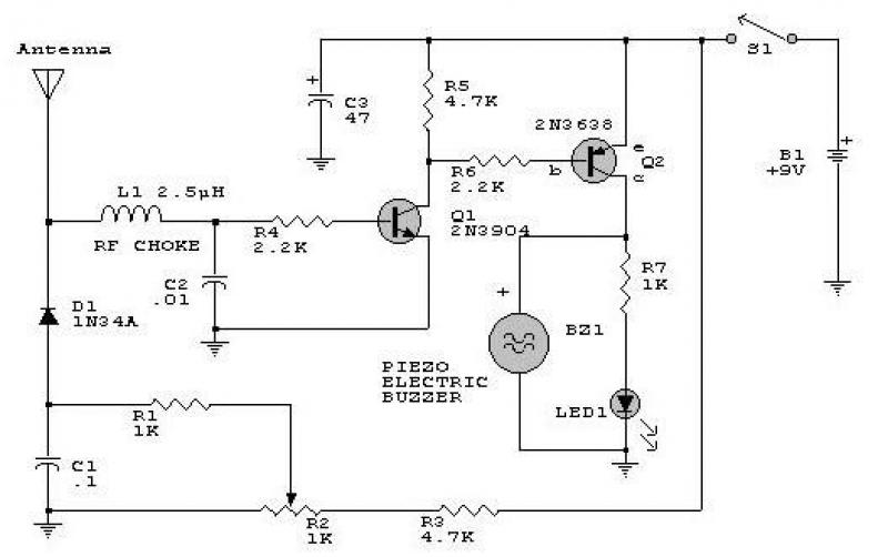
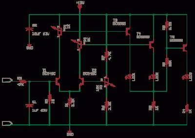
This RF signal detection circuit is designed to operate over a wide frequency range, specifically from below the standard broadcast band up to 500 MHz. The circuit utilizes a combination of transistors to amplify the incoming RF signals, allowing for effective detection of both weak and strong signals. The visual indication is provided by an LED, which lights up when an RF signal is detected, while an audible indication can be achieved through a connected speaker or buzzer.
The circuit's sensitivity can be fine-tuned using a potentiometer (R2), which adjusts the bias of diode D2. This flexibility enables the user to optimize the detection capability according to the specific application or environment. A critical consideration in the circuit design is minimizing stray inductance, which can adversely affect performance. Therefore, it is recommended to keep the leads of the diode and capacitor (C1) as short as possible.
For the transistors, various high-gain options are available. For the PNP transistor (Q2), suitable choices include the 2N3906 or 2N2907. For the NPN transistor (Q1), options such as the PN2222A or 2N3904 are recommended. The selection of these components will influence the overall gain and performance of the circuit, making it essential to choose transistors that meet the required specifications for the intended application.
Overall, this circuit serves as a versatile solution for RF signal detection, providing both visual and audible feedback while allowing for sensitivity adjustments to cater to various detection scenarios.This circuit responds to RF signals bellow the standard broadcast band to over 500MHz and provides an visual, and audible indication when the rf signal is detected. By adjusting the bias of D2 with the R2 potentiometer the circuit can detect low power or strong signals.
A very sensitive setting can be obtained by modifying R2 until the LED begins
to light. Keep diode and capacitor (C1) leads short to minimize stray inductance. The used transistors can be: 2N3906, 2N2907 or other PNP high gain transistor for Q2 and PN2222A, 2N3904 or other NPN high gain transistor for Q1.
🔗 External referenceRelated Circuits
An FM modulator that modulates a carrier frequency with the composite signal, and an RF amplifier that provides enough power to be transmitted through an antenna. Here is the schematic diagram of the FM transmitter circuit: The core of...
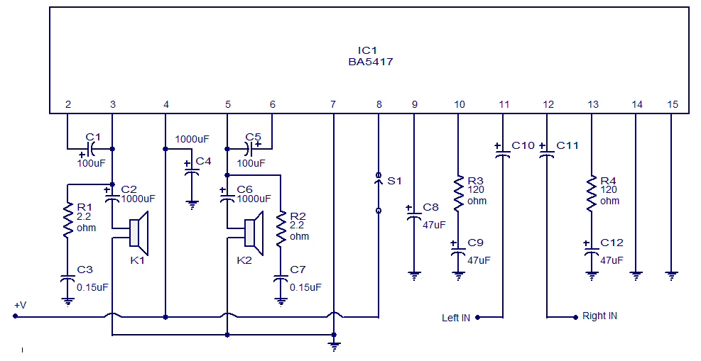
The BA5417 is a stereo amplifier integrated circuit (IC) that features several advantageous characteristics, including thermal shutdown, a standby function, soft clipping, and a wide operating voltage range. It can deliver 5 watts per channel into 4-ohm loudspeakers when...
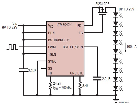
The LTM8042 integrates a boost power topology with a unique current loop to function as a constant-current source. The PWM input allows for LED dimming ratios of up to 3000:1, while analog dimming can be achieved with a single...
This is a constant current source using a FET. It serves as a simple replacement for a series resistor to limit current. The N-Channel FET BF256C can provide a current of 15mA. Before using integrated circuits, it is advisable...

This 1000-watt power inverter circuit diagram is based on the MOSFET RF50N06. For increased power output, additional MOSFETs can be paralleled with the RF50N06. These MOSFETs are rated for 60 volts and 50 amps. It is essential to connect...
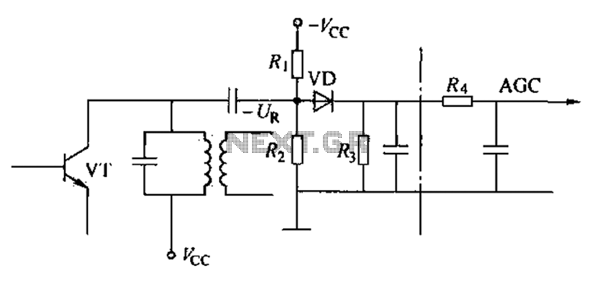
Commonly referred to as an automatic gain control (AGC) circuit, it is primarily utilized in receivers. This circuit maintains a constant output voltage amplitude despite variations in the input signal amplitude. It ensures that the receiver can effectively process...