
Phone line Audio Visual Ringer
The circuit described functions as an auxiliary telephone ringer, allowing users to be alerted to incoming calls from a remote location. The design incorporates a simple parallel connection to existing telephone lines, utilizing twin flexible wires to integrate seamlessly without the need for an external power source.
The visual indication of an incoming call is achieved through a combination of resistor R1, diodes D5, and LED1, which illuminate when the telephone rings. The core of the audio alert system is centered around the integrated circuit IC1, either the BA8204 or ML8204, which is specifically designed for generating bell sounds in telecommunication applications. This IC is housed in an 8-pin mini DIP package, making it compact and easy to handle.
Resistor R3 is critical for adjusting the sensitivity of the bell, allowing customization based on user preference or environmental factors. The tone of the bell is controlled by resistor R5 and capacitor C4, which determine the frequency output, while resistor R4 and capacitor C3 manage the repeat frequency of the ringing sound. This flexibility enables users to experiment with different component values to achieve a tone that is most pleasing or suitable for their environment.
The operational principle of the circuit is straightforward. An incoming bell signal, typically around 75V AC, is routed through capacitor C1 and resistor R2, which then feeds into a diode bridge formed by diodes D1 through D4. This arrangement rectifies the AC signal into a DC output, which is subsequently smoothed by capacitor C2 to ensure stable operation.
The dual-tone ring signal is produced at pin 8 of the IC1, with the volume of the output sound being adjustable via a variable resistor (VR1). The final audio signal is delivered to a piezo-ceramic sound generator, which converts the electrical signal into audible sound, alerting users to incoming calls effectively. This circuit design combines simplicity and functionality, making it an ideal solution for enhancing telephone alert systems in various settings.Many a times one needs an ex- tra telephone ringer in an ad- joining room to know if there is an incoming call. For example, if the telephone is installed in the drawing room you may need an extra ringer in the bedroom.
All that needs to be done is to connect the given circuit in parallel with the existing telephone lines using twin flexible wires. This circuit does not require any external power source for its operation. The section comprising resistor R1 and diodes D5 and LED1 provides a visual indication of the ring. Remaining part of the circuit is the audio ringer based on IC1 (BA8204 or ML8204). This integrated circuit, specially designed for telec- om application as bell sound generator, requires very few external parts.
It is readily available in 8-pin mini DIP pack. Resistor R3 is used for bell sensitivity adjustment. The bell frequency is controlled by resistor R5 and capacitor C4, and the repeat frequency is controlled by resistor R4 and capacitor C3. A little experimentation with the various values of the resistors and capacitors may be carried out to obtain desired pleasing tone.
Working of the circuit is quite simple. The bell signal, approximately 75V AC, passes through capacitor C1 and resistor R2 and appears across the diode bridge comprising diodes D1 to D4. The rectified DC output is smoothed by capacitor C2. The dual-tone ring signal is output from pin 8 of IC1 and its volume is adjusted by volume control VR1.
Thereafter, it is impressed on the piezo-ceramic sound generator. 🔗 External reference
Related Circuits
This reference design demonstrates the MAX98400 Class D audio amplifier in a stereo audio docking station application. The demo box is a powered speaker dock that drives a speaker system consisting of 2-inch satellite speakers and a 5-inch subwoofer. The...
Micropower and low-voltage operational amplifiers enable the construction of high-performance analog signal processors that do not require batteries or wall transformers. Instead, a capacitor can serve as the power source. The circuit illustrated in Figure 1 depicts an analog...
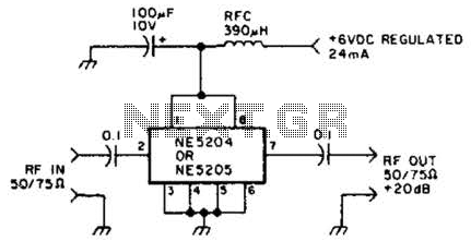
The Signetics NE5204 or NE5205 can be utilized in this audio frequency to 350-MHz (-30 dB) preamplifier. For a requirement of 600 MHz at 3 dB, the NE5205 should be employed. The noise figure is 4.8 dB at 75...
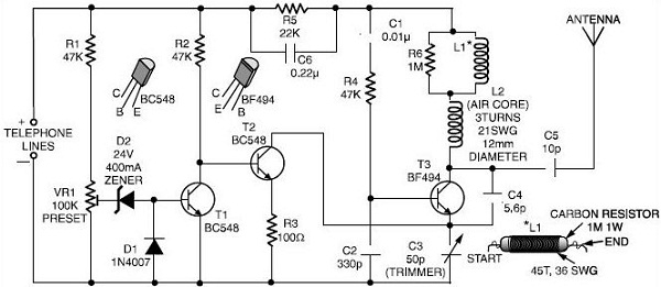
This schematic outlines a simple FM transmitter designed to operate using a phone line for both power and audio signal reception. By connecting the device to the desired phone line, it enables monitoring of conversations. Users can tune their...
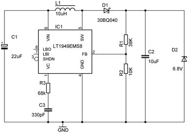
The phone is a Siemens S65. The official charger that came with the phone specifies an output of 5V at 420mA. However, actual performance may vary from the printed specifications. Voltage measurements indicated that without the phone connected, the...
With the amount of equipment in home entertainment centers today the need to be able to vary the gain of the audio or video signal is needed. I found this particular circuit helpful when used in conjunction with the...