
Portable phone charger
The circuit design incorporates a switching step-up converter to effectively boost the voltage from two AA batteries to the necessary level for charging the Siemens S65 phone. The LT1949 converter is chosen for its efficiency and ability to operate at low input voltages, making it ideal for battery-powered applications. The output stability is enhanced by the use of a ceramic capacitor, which provides low equivalent series resistance (ESR), ensuring minimal voltage ripple during operation. The inclusion of a Zener diode adds an extra layer of safety, preventing overvoltage conditions that could potentially damage the phone's battery management system. The compact design of the PCB facilitates easy integration into portable applications, while the careful selection of components ensures reliable performance and longevity of the charging circuit. Overall, this circuit not only meets the voltage requirements for the Siemens S65 but also demonstrates a practical approach to managing power from common battery sources.The phone is a Siemens S65. The official charger that came with the phone says 5V at 420mA. Because these things do not always actually deliver what is printed on them I measured the voltage myself. This is actually quite hard with the tiny contacts on the connector, especially when it also has to be plugged into the phone.
Without a phone connected the voltage was much higher, around 8V if I remember correctly. When the phone was actually connected the voltage would drop to around 4V and even lower. The label says output: `5V-11V DC 350mA`. Of course I opened this thing to look what was inside. I found a cheap looking PCB with a step-down converter based on Motorola`s well known MC34063. Based on the component values it was configured for a 8. 75V output and a current limit of 320mA. When connected to the phone the voltage drops below 5V because the current limit is reached. To see at what voltage the phone starts charging I cut off the connector from the car charger and put 5V on it. The phone did not started charging. At 5. 5V still nothing, but at 6V it started charging. As was shown with both the official charger and the cheap car charger, once the phone starts charging the voltage may get well below 5V without problems.
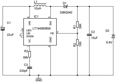
But it needs around 6V to get started. To get 6V out of two AA batteries I used a LT1949 switching step-up converter from Linear Technology. An AA battery typically delivers about 1. 2V-1. 5V but the voltage drops even lower under load and as they discharge. The LT1949 already runs at a voltage of 1. 5V so two AA batteries are enough to keep it running, even at low battery voltages. The IC has an internal switch current limit of about 1. 1A. This will limit the output current. In fact, the phone tries to use so much current that the current limit kicks in and the output voltage drops below 6V.
As the official charger does the same this is not a problem. The current limit is by design and does not harm the IC. The schematic is quite simple and follows the typical application schematic from the datasheet: The schematic lacks a symbol for the power in and out points (mainly because the PCB layout does not really have any connectors for them) but obviously power goes in on the top left (Vin pin) and comes out at the top right. Low battery and shutdown pins are unused and can be left floating. The part list is short: I use SMD most of the time anyway but in this case this really keeps everything small.
The IC itself has a 0. 5 mm pitch and is very small, the inductor from Sumida is relatively small thanks to the high switching frequency (600kHz). The schottky diode could be replaced by something smaller but I had this type lying around, its a pretty good diode.
The output is stable with a 10uF ceramic capacitor, I used a panasonic one in a 0805 package. For the input a low ESR tantalum is used from the TPS series. The zener diode is an extra protection, just in case something goes wrong with the step-up converter this diode will provide some protection for my phone against voltages higher than 6. 8V. The drilled holes will be used to put some copper wire in that will hold the power wires to the PCB. This way the soldered connections will not break easily if you pull the wires accidently. 🔗 External reference
Related Circuits
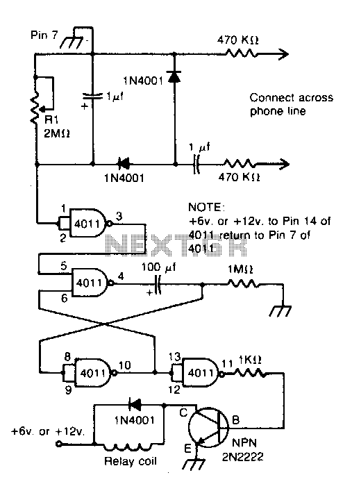
Connected across the bell circuit of a phone, this circuit activates a relay when the phone is ringing. It can utilize delay contacts to operate any bell, siren, buzzer, or lamp. The described circuit functions as a relay activation mechanism...
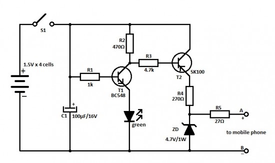
This is an ideal mobile charger that utilizes 1.5-volt pen cells to charge mobile phones while traveling. It can replenish a cell phone battery three or four times. The mobile charger circuit is designed to be compact and portable, making...
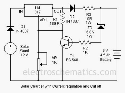
A solar charger circuit is designed to charge lead-acid batteries or nickel-cadmium (Ni-Cd) batteries using solar power. This circuit captures solar energy to charge a 6-volt, 4.5 Ah battery for various applications. It features voltage and current regulation along...
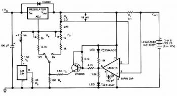
The following circuit illustrates a 1.5 V Lead-Acid Battery Charger Circuit Diagram. Features include a comparator output that controls the voltage regulator. The 1.5 V Lead-Acid Battery Charger Circuit is designed to efficiently charge lead-acid batteries while ensuring optimal voltage...
It's just a simple power supply with a 7805 regulator. The chip must be mounted on a large metal radiator because the current requested by the regulator is near 0.4 A. However, to lower the power, you can put...
This article discusses a fully automatic 6V 4.5AH battery charger circuit that utilizes the LM317T integrated circuit along with a few additional components. The circuit is designed to charge a 6V lead-acid battery. The circuit utilizes the LM317T voltage regulator,...