
Telephone FM transmiter
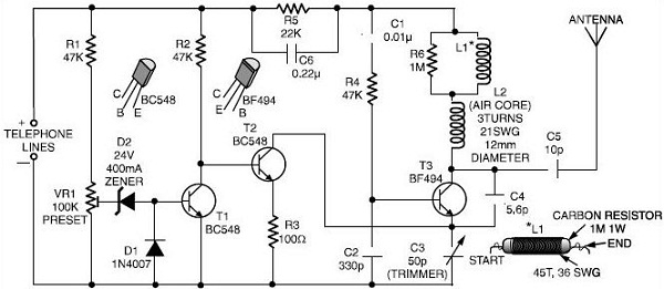
The FM transmitter circuit utilizes a few essential components to function effectively. Primarily, it consists of a microphone for audio input, an oscillator to modulate the audio signal onto a carrier frequency, and a power supply derived from the phone line itself. The microphone captures sound waves, converting them into electrical signals. These signals are then fed into the oscillator, which modulates the audio onto a specific frequency, allowing it to be transmitted wirelessly.
The power supply is crucial, as it draws voltage from the phone line, typically around 48 volts DC when the phone is in use. A voltage regulator may be included in the circuit to ensure that the components operate within their specified voltage limits. The transmitting frequency should be chosen carefully, often within the FM band (88 MHz to 108 MHz), to ensure compatibility with standard FM receivers.
A simple antenna, often a wire of appropriate length, is connected to the output of the oscillator to radiate the modulated signal. The range of the transmitter can vary based on the antenna design and the power output, but it typically allows monitoring within a few hundred feet.
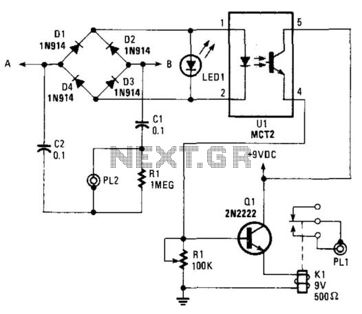
To ensure efficient operation and minimize interference with other devices, proper shielding and grounding techniques should be employed. Additionally, it is essential to consider legal implications when constructing and using such devices, as unauthorized interception of communications may violate privacy laws.If you ever wondered how those phone bugs from spy movies work, here is the schematic for your very own. This simple FM transmitter uses a phone line to both power the device and receive the audio signal. Just hook it up to the phone line you want to monitor and tune your FM radio receiver to the transmitting frequency.
If you still have a. 🔗 External reference
Related Circuits
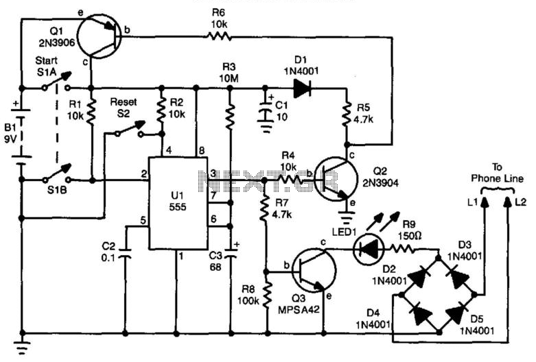
If a user is busy and cannot answer or does not wish to answer their phone, this circuit will emit a busy signal without requiring the phone to be left off the hook. After a predetermined duration, the circuit...
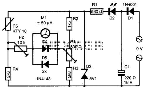
The telephone line tester comprises a meter used to measure line voltage in both the on-hook and off-hook states, three resistors (including one variable resistor), a pushbutton switch, and a modular telephone connector. When the circuit is connected to...
The telephone ring generator shown below generates the needed high voltage from a simple switching mode power supply (SMPS) which employs a CMOS Schmitt Trigger square wave oscillator, 10 mH inductor, high voltage switching transistor (TIP47 or other high...
A teleremote circuit enables the switching on and off of appliances through telephone lines. It can be used to control appliances from any distance, overcoming the limited range of infrared and radio remote controls. The circuit can switch up...

Electronic FM Telephone Transmitter Schematic. The following schematic design illustrates a circuit diagram for an FM telephone transmitter built on a compact PC board layout. This small design allows it to be easily integrated within the housing of a...
This circuit operates on the ringing voltage of the telephone to trigger a tape recorder to record messages. It can be made to latch using extra contacts if the tape recorder requires a constant-contact closure. The circuit utilizes the ringing...