
Phone line-powered flashlight
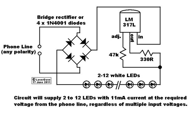
This circuit design integrates a phone line interface with LED indicators, ensuring that the phone line remains operational while providing visual feedback through LEDs. The circuit is designed to handle the unique voltage characteristics of telephone lines, which deliver 48V DC under normal conditions and can spike to 96V AC when the phone rings.
The LM317 voltage regulator is employed in this application primarily as a current limiter for the LEDs. It is crucial to note that the LM317 has a maximum input voltage rating of 40V; thus, exceeding this voltage can lead to damage. In this case, the phone line's voltage, particularly during ringing, can exceed this threshold, necessitating the use of a bridge rectifier to protect the LM317 from overvoltage conditions. The bridge rectifier converts the AC ringing voltage into a usable DC voltage, allowing the LM317 to function within its safe operating range.
In the schematic, the LEDs are arranged in series, and the configuration allows for their operation while maintaining the integrity of the phone line. The circuit should be designed to ensure that when the phone is picked up, the voltage drop across the LEDs is sufficient to turn them off, allowing for normal phone operation. The current limiting feature of the LM317 ensures that the LEDs are not subjected to excessive current, which can lead to premature failure.
The correction in the hookup instructions is critical for proper circuit functionality. The negative pin of the last LED must be connected to the negative pole of the bridge rectifier, while the positive pole of the bridge should connect to the input pin of the LM317. This configuration ensures that the circuit operates correctly and prevents potential damage to the components.
In summary, this circuit exemplifies a practical application of the LM317 voltage regulator in conjunction with a bridge rectifier to interface with a telephone line, allowing for visual indication via LEDs without compromising the functionality of the phone line. Proper attention to voltage ratings and circuit connections is essential for reliable operation.This works in a way that the phone line won`t stay busy while the LEDs are connected and when you pick up the phone, the light goes off and allow you to use your phone normally. hello. u sadi that ur phone delivers 48 v DC n when phone rings, it delivers 96 v AC. right. ! can u plz explain how dis hapend r else send me a link twhich related to this. ! as soon as possible i built this circuit. but output of my LM 317 shows a voltage of 0. 08. my friend told me that my LM 317 was fried up by high input voltage. is that so. my telephone line voltage in normal condition is 52V. So i need to know what`s the maximum input voltage of LM 317 The line is at 48 volts but RISES to 96 volts when you pick it up What kind of phone system is this Normally the voltage drops to around 6 to 9 volts while in use. The ringer voltage is about 90 to 135 VAC. You will find that only 2 are used, does not matter if they are reversed as the circuit have a bridge.
One thing I cannot work out, How do the leds go out on higher voltage, the voltage regulator is wired as a current limiter. LEDs work correctly when are connected in series ! In our country there are 36V AC in phone line, and it raise to 96V AC when ring. Without Diode bridge LM317 will be caput! Why we use LM317 as current regulator Overvoltage must defect the leds. I preffer to use it like voltage regulator, and serial connected leds will be fine :) See datasheet for more info -> In my earlier post, I forgot to mention that your description of the hookup has a small but significant error.
Your schematic is correct, but you describe the hook up as "-Solder the negative pin of the last LED to the positive pole of the bridge and solder the negative pole of the bridge to the input pin of the LM317". It *should* be - Solder the negative pin of the last LED to the NEGATIVE pole of the bridge, and solder the POSITIVE pole of the bridge to the input pin of the LM317.
COOL TIP: Any electronic project that you make that requires batteries or an AC adapter could benefit by having an inexpensive bridge rectifier as the power input. This prevents any possibility of damage from putting batteries in backward, and it also prevents damage from using the wrong AC adapter.
Most adapters have a center-positive, but some also have center-negative. If you use the wrong one, your unit is toast - but with a bridge it will never be. 🔗 External reference
Related Circuits
This circuit can manage nine independent telephones using a single telephone line pair, located up to 100 meters apart for making and receiving calls while ensuring conversation privacy. It is particularly useful for multiple members residing in different rooms...
Mobile phone battery chargers available in local markets can be quite expensive. The circuit presented here offers a low-cost alternative for charging cellular phone batteries or battery packs with a rating of 7.2 volts. This low-cost phone battery charger circuit...
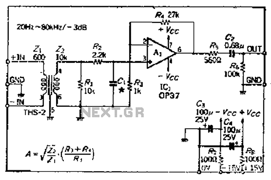
The common mode signal rejection ratio is influenced by the input transformer, which should either be a commercially available or a well-balanced homemade transformer. It is important to note that as frequency increases, the balance may decrease. The transmission...
The idea behind the portable DAC is to get better sound than from the line out or headphone out of portable CD player, a pc sound card or other digital audio source. Many of us want to listen to...
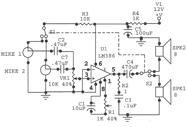
The LM386 is an ideal choice for a door phone application. This device is particularly beneficial in modern urban households, utilizing a condenser microphone and a speaker. The LM386 is a low-voltage audio power amplifier that is commonly used in...
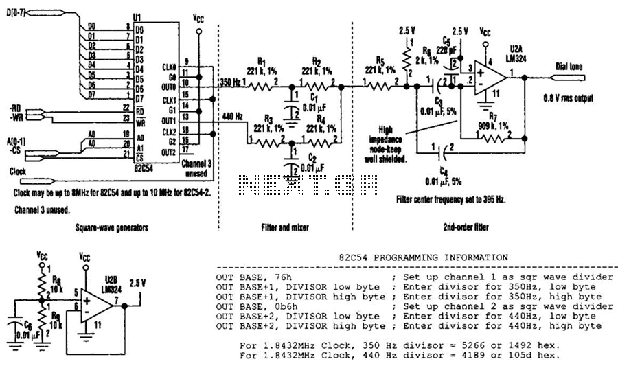
This pager allows the use of in-house phone wiring as a public address (PA) system. It utilizes two tone decoders to detect a specific touch-tone key, which activates an audio amplifier. The described system integrates existing telephone wiring to function...
Warning: include(partials/cookie-banner.php): Failed to open stream: Permission denied in /var/www/html/nextgr/view-circuit.php on line 713
Warning: include(): Failed opening 'partials/cookie-banner.php' for inclusion (include_path='.:/usr/share/php') in /var/www/html/nextgr/view-circuit.php on line 713