
The input circuit common mode noise suppression microphone amplifier with balance
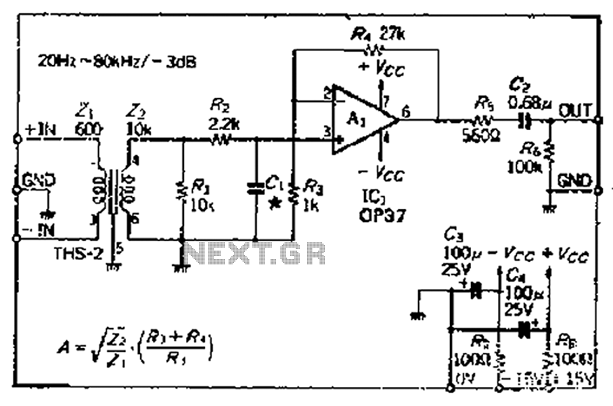
The circuit design focuses on optimizing the common mode signal rejection ratio through the careful selection and configuration of transformers and operational amplifiers. The use of a THS-2 transformer with a specified impedance ratio enhances the performance, particularly in applications requiring high fidelity and low noise levels. The step-up ratio derived from the transformer’s turns ratio plays a crucial role in determining the voltage gain, which is essential for ensuring that the signal remains strong enough for further processing.
Resistance values in the circuit are critical, as they directly influence the frequency response and overall performance of the transformer. The low-pass filter implemented serves to minimize high-frequency noise, allowing for clearer signal transmission. The choice of the OP37 operational amplifier is significant due to its low noise characteristics, which are vital in sensitive applications where signal integrity is paramount. The configuration of the amplifier in a closed-loop manner ensures stability and enhances the frequency response, making it suitable for high-performance audio or data acquisition systems.
In cases where a high offset voltage is present, the inclusion of a series capacitor is recommended to mitigate potential issues caused by DC offsets, ensuring that the signal remains within the operational limits of the amplifier. This careful consideration of component selection and circuit configuration is essential for achieving optimal performance in electronic systems that require high levels of signal integrity and noise reduction. Because the common mode signal rejection ratio depends on the input transformer, it should be used or homemade good balance transformer (It should be noted l frequency increase s, the balance will fall), is determined to consider the transmission frequency range boost ratio. Step-up ratio is primary to secondary turns ratio. Terminal can also be used to represent the square root of the impedance ratio. The circuit uses a utility available on the market THS-2 transformer impedance ratio of 6000: iookQ, so the boost ratio:/1 xo Lily F4, this kind available 12dB voltage gain from the input conversion noise this point look relatively favorable. Resistance R, and in the sub-Yi across the transformer, it seems no need to use iokfl, but the frequency characteristics of the transformer with a resistance value becomes, so the frequency characteristics measured to determine a post- chu t, cl high noise suppression is a low-pass filter for high inhibition effect depends dry cl, Zhang Rz available plus the equivalent output resistance is obtained.
OP zoom uses a closed-loop frequency characteristics of a good low-noise type OP37, straight surprised coupling. If you use a high OP amplifier offset voltage, should the series with a roar of dozens of micro-ho capacitance mouth
Related Circuits
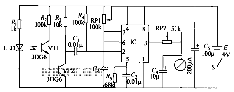
Cycling is a common mode of transportation. When paired with a bicycle speedometer, cyclists can effectively monitor their speed, which is particularly beneficial for training purposes. The bicycle speedometer circuit, as illustrated in Figure 5-33, utilizes the relationship between...
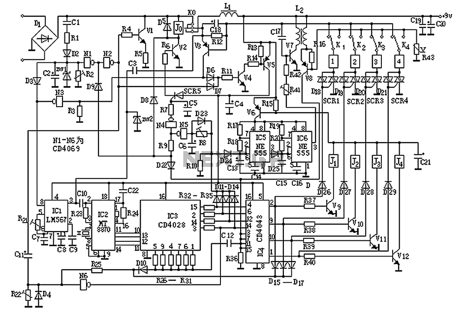
The circuit operates by sending ringing pulses through capacitor C1, resistor R1, and diode D2 to charge capacitor C2 to a voltage of 6V. This voltage causes transistors N1 and N2 to reverse, which activates V1, the analog hook,...
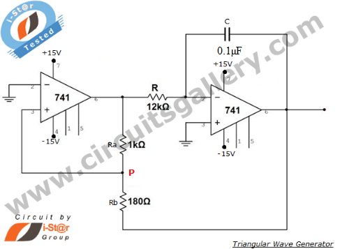
An operational amplifier-based triangular waveform generator is a simple circuit that is widely used in function generators. This circuit utilizes the 741 operational amplifier to create a triangular wave generator. The output waveform of an integrator will be triangular...
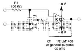
This simple filter utilizes an RC section as the filter element, incorporating a voltage follower to manage other frequencies. The -3 dB point is calculated as 1/(6.28 * RXCV), resulting in a response that drops 6 dB per octave...
This reference design demonstrates the MAX98400 Class D audio amplifier in a stereo audio docking station application. The demo box is a powered speaker dock that drives a speaker system consisting of 2-inch satellite speakers and a 5-inch subwoofer. The...
This project will explain how you can build a receiver for 35MHz. The receiver is based on the FM receiver circuit MC3371, and the frequency is PLL controlled with LMX2306 circuit. In this project, a radio receiver for RC...
Warning: include(partials/cookie-banner.php): Failed to open stream: Permission denied in /var/www/html/nextgr/view-circuit.php on line 713
Warning: include(): Failed opening 'partials/cookie-banner.php' for inclusion (include_path='.:/usr/share/php') in /var/www/html/nextgr/view-circuit.php on line 713