
Low Cost Phone Battery Charger Schematic Diagram
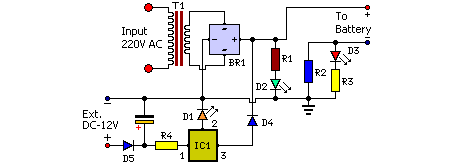
This low-cost phone battery charger circuit is designed to provide an efficient and economical solution for charging mobile phone batteries. It operates at a voltage of 7.2 volts, making it suitable for various types of mobile phones and battery packs that operate within this voltage range.
The circuit typically consists of a transformer, a bridge rectifier, a voltage regulator, and some passive components such as resistors and capacitors. The transformer steps down the AC mains voltage to a level suitable for charging. The bridge rectifier converts the AC voltage to DC, which is necessary for charging the battery.
A voltage regulator is employed to ensure that the output voltage remains stable at 7.2 volts, preventing overcharging and potential damage to the battery. Additional components may include diodes for reverse polarity protection and capacitors to smooth out any fluctuations in the output voltage.
This charger circuit can be constructed using readily available components, making it accessible for hobbyists and engineers looking for a cost-effective charging solution. Proper attention to safety and adherence to electrical standards is crucial when assembling and using this circuit to ensure reliable operation and user safety.Mobile phone, phone battery chargers on hand wearing the souk are quite expensive. This circuit presented at juncture comes so a low-cost alternative to charge cellular phone telephones/battery packs with a rating of 7. 2 volts. You are reading the Circuits of Low Cost Phone Battery Charger And this circuit permalink url it is 🔗 External reference
Related Circuits
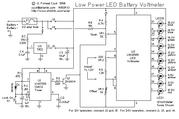
This is a low-power voltmeter circuit suitable for alternative energy systems operating on 12-volt and 24-volt batteries. The voltmeter features an expanded scale design, allowing it to display small voltage increments within the 10 to 16-volt range for 12-volt...
The 900 Hz tone is generated using an LC oscillator. The inductive component, "L," is provided by the inductance of the oscillator's output coupling transformer T1. This configuration is a variation of one of the two standard Hartley oscillator...
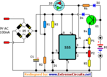
This automatic NiCd charger for 9V NiCd batteries utilizes the properties of a 555 timer and is straightforward to construct. The design allows for continuous charging of the battery without the risk of overcharging or discharging. With the specified...
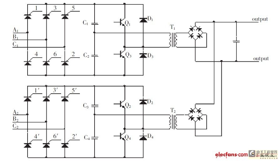
The high-pressure direct current power supply has become increasingly widespread. This system outputs in parallel with double-channel power to achieve low ripple direct current. In situations where gas switching tube frequency is limited, this method can generate low ripple...
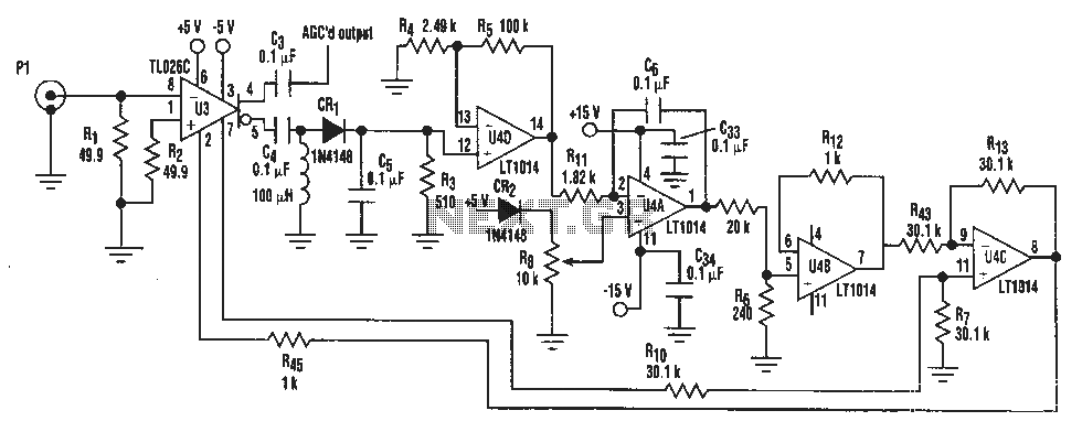
A simple IF AGC signal with a wide dynamic range and excellent linearity characteristics may be composed of two chips: the TL026C T1 voltage control amplifier IC and the LT1014 (or any other similar basic quad op amp device). The...
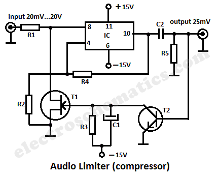
This audio limiter circuit is simple to construct and is compatible with BA741 operational amplifiers, whether in 8-pin or 4-pin configurations. It requires a symmetrical power supply. The circuit is designed to manage audio input levels effectively. The audio limiter...
Warning: include(partials/cookie-banner.php): Failed to open stream: Permission denied in /var/www/html/nextgr/view-circuit.php on line 713
Warning: include(): Failed opening 'partials/cookie-banner.php' for inclusion (include_path='.:/usr/share/php') in /var/www/html/nextgr/view-circuit.php on line 713