
Phono Preamplifier
Expanding on this, the circuit's efficiency is largely due to its simple design, which includes a phono preamplifier that is adept at handling the demands of older vinyl records. The moving-magnet cartridges, which are a popular choice due to their affordability, contribute to the overall effectiveness of the circuit. This is particularly true when the circuit is used in conjunction with audio power amplifiers, as the description suggests.
The low noise characteristic of the circuit ensures a clean, clear audio output, free from unwanted interference. This is complemented by the accurate RIAA frequency response curve which ensures a faithful reproduction of the audio signal across the full range of audible frequencies. Moreover, the minimal distortion characteristic of the circuit ensures that the audio output remains true to the original recording, without any unwanted alterations or colorations.
The circuit's strong performance in handling high frequency transients, due to the passive equalization in the 1 to 20KHz range, is a key factor in its ability to deliver a high-quality audio output. This ensures that the audio signal remains stable and consistent, even when dealing with complex or demanding audio material.
The final element of the circuit, the transistors and associated components, provide a ± 18V supply to the op-amp. This not only improves the headroom, allowing for greater dynamic range in the audio signal, but also enhances the maximum output voltage, ensuring that the circuit can deliver a powerful audio output when required.In recent years, following CD`s introduction, vinyl recordings are almost disappeared. Nevertheless, a phone preamplifier is still useful for listening old vinyl discs from a well preserved collection. This simple but efficient circuit devised for cheap moving-magnet cartridges, can be used in connection with both audio power amplifiers shown in preceding pages, featuring low noise, good RIAA frequency response curve, low distortion and good high frequency transients behavior due to passive equalization in the 1 to 20KHz range.
Transistors and associated components provide ± 18V supply to the op-amp, improving headroom and maximum output voltage. 🔗 External reference
Related Circuits
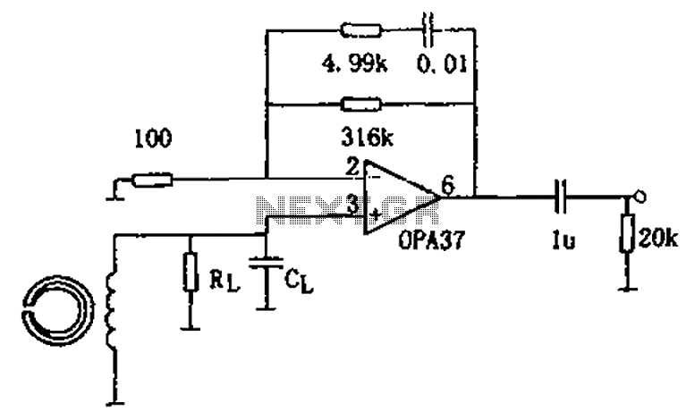
The circuit is a 90s common recorder head amplifier circuit that utilizes the ultra-low noise precision operational amplifier OPA37 as a preamplifier. This circuit is capable of providing standard NAB equalization. At a frequency of 1 kHz, it achieves...
Adapting a failed Tesla coil into a crystal radio set for demonstration purposes has presented challenges, particularly with antenna size for optimal signal reception. It has been noted that an ideal AM antenna should range between 100 to 500...
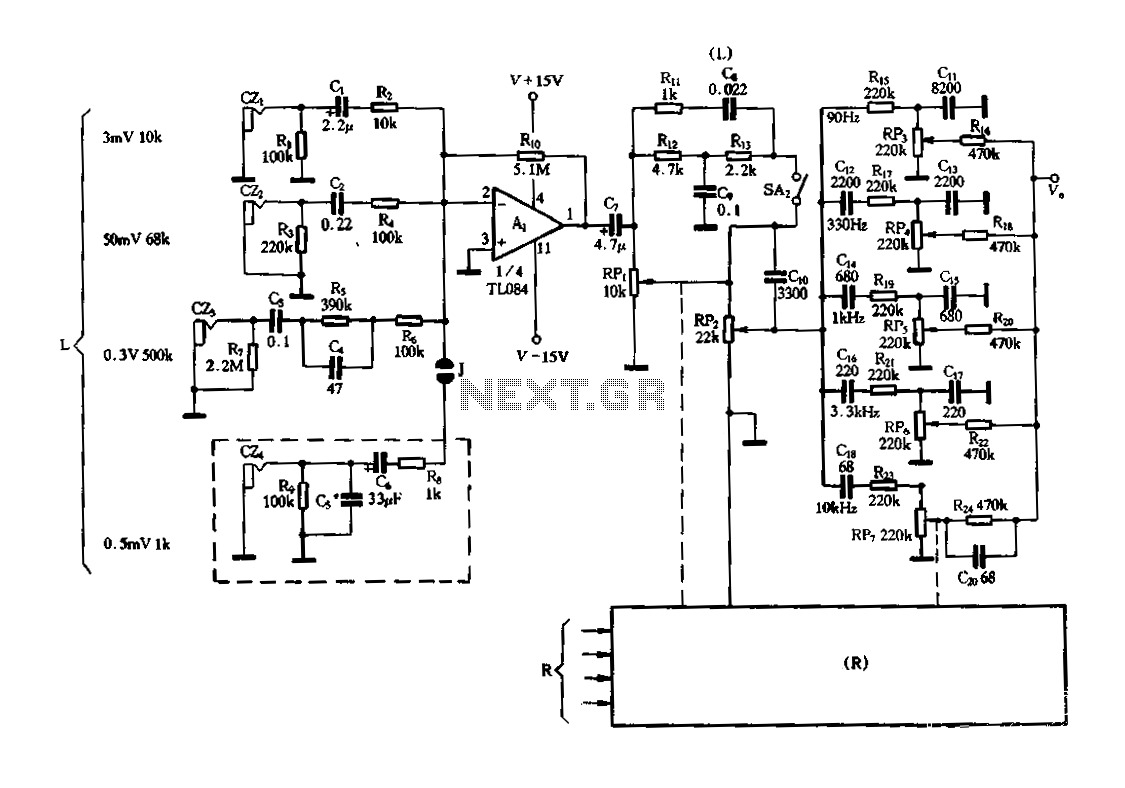
Figure 3-25 illustrates a hybrid circuit featuring four input preamplifiers. The components C1, C2, C3, and C4 can accept signals from a microphone, line, phono, and crystal head respectively. The configuration allows for the individual or simultaneous entry of...
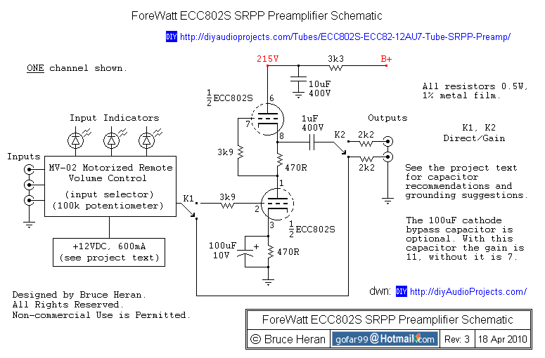
The project involves a shunt-regulated push-pull (SRPP) driver stage. Research and modeling have been conducted on the SRPP, highlighting its advantages, which include good linearity, low distortion, low output impedance, effective power supply noise rejection, and moderate gain. The...
The preamplifier that appears in the figure is a completely symmetrical preamplifier, from the input as the exit and it works in Class A. It does not have somebody innovation, simply it uses good solutions, in order the result...
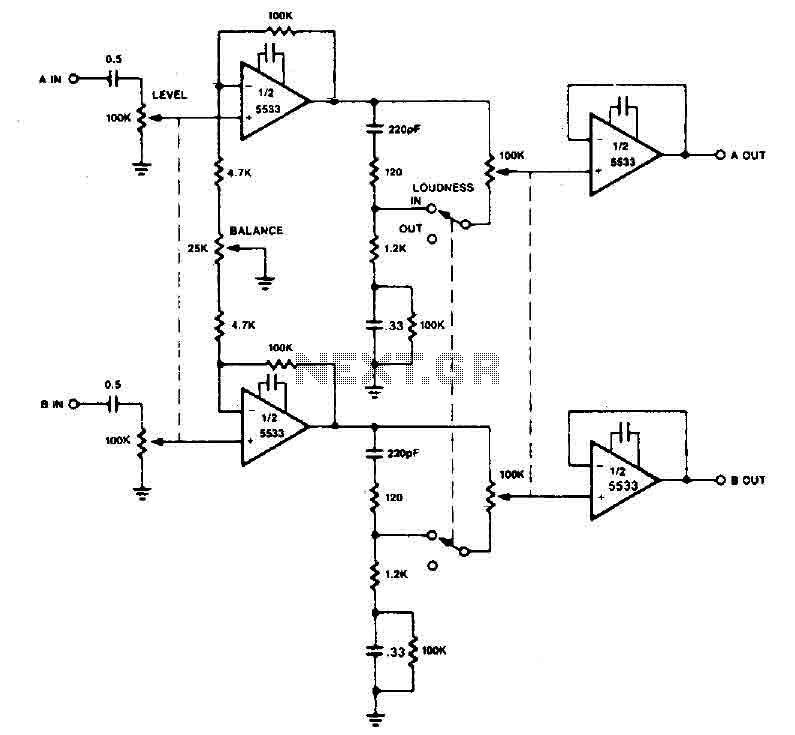
The preamplifier circuit utilizes the 5533 chip and incorporates a combination of balance and volume controls. Given the nonlinearity of the human auditory system, low frequencies are required to be amplified at lower listening levels. Additionally, level and LOUDNESS...