
DIY ECC802S (12AU7 / ECC82) Vacuum Tube SRPP Preamplifier
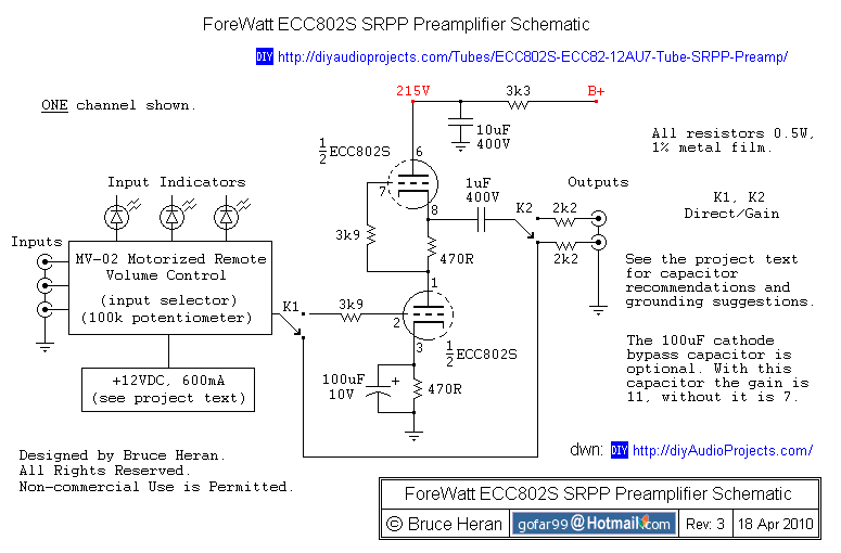
The SRPP (shunt-regulated push-pull) driver stage circuit is designed to provide a high-quality audio signal amplification while maintaining low distortion and noise. The SRPP configuration employs two vacuum tubes, configured in a way that allows for balanced drive to the output stage. This configuration offers several advantages, including improved linearity and a lower output impedance, which is critical for driving subsequent stages in audio applications.
In the design, the ECC802S vacuum tube is utilized due to its favorable amplification factor, which aligns well with the gain requirements of the circuit. The selected tube should ideally have an amplification factor around twice the desired gain, ensuring that the circuit operates efficiently within its linear range. The use of a modeling program is recommended to simulate the circuit behavior before physical implementation, allowing for adjustments to component values and configurations to optimize performance.
To achieve the desired signal-to-noise ratio of approximately 90 dB, careful attention must be paid to component selection. High-quality resistors and capacitors are essential to minimize noise and distortion. The design should also incorporate filtering techniques to prevent interference from RF signals and other unwanted frequencies, ensuring that the audio signal remains clean across the entire frequency range from below 20 Hz to at least 20 kHz.
The output stage of the SRPP is characterized by its ability to drive low-impedance loads effectively, making it suitable for various applications. The decision to utilize solid-state rectifiers instead of tube rectification is driven by the need for reliability and performance consistency. Solid-state devices, particularly fast-recovery types, provide efficient power supply regulation, which is crucial for maintaining the stability of the audio signal.
The project features two distinct preamplifier designs. The first design showcases the tubes externally, providing a visual appeal, while the second design encloses the tubes within the chassis for a more streamlined look. The enclosed preamp also integrates modern features such as wireless remote control for volume and input selection, enhancing user convenience.
Overall, this SRPP driver stage circuit exemplifies the integration of traditional vacuum tube technology with contemporary design elements, resulting in a high-performance audio preamplifier capable of delivering exceptional sound quality while maintaining user-friendly functionality.that used a SRPP (shunt-regulated PP) driver stage I started to do some research and modeling on a SRPP. The advantages of such a line stage are much the same as those when a SRPP is used as a driver. Good linearity, low distortion, low impedance output, good power supply noise rejection and modest gain.
The research also indicated that the gain n eeded was usually between 3 and 10. This is a perfect application for a tube SRPP. There are many ways to determine what tubes to use in any given project and a line stage is certainly no exception. My method is to determine how much gain I need and then select a tube that has an amplification factor of about twice what I need.
The gain in this case fit right in with one of my favorite tube types the ECC802S. The ECC802S is a variation of the 12AU7 / ECC82 family of vacuum tubes. Others may prefer different tubes but I have had good success with the ECC802S from JJ/Tesla. The actual design process for a SRPP stage is really best started with some type of modeling program. Otherwise you will probably have to make many test set ups to find good values for the components. If you don`t have a distortion analyzer, good dual trace oscilloscope scope and low distortion signal generator, you will be in for a lot of trial and error (mostly error) to get something reasonable.
I also considered using a Mu-follower stage. This is quite similar to a SRPP and often has some advantages (like lower output impedance). In the long run I was unable to come up with a Mu stage that I felt performed better than the SRPP. Warning: This project is based on the use of vacuum tubes and contains potentially dangerous voltages. If you are unfamiliar with the hazards or uncomfortable working with such voltages, please don`t risk your health or possibly life building the preamp.
For those of you who have looked at some of the other projects I have designed you are familiar that I insist that the end project have certain qualities. It must be quiet. I hate hum and noise. A signal to noise ratio of around 90 dB seems to suit me. More is better. The response must go from below 20 Hz to at least 20 kHz within 1 dB. Most of my projects are flat down to 10 Hz and go well past 20 kHz. I actually design in some high filter aspects so that the preamplifier will not pick up radio stations and other junk above audio frequencies.
Distortion must be low. For a valve tube amp a maximum of 1% at full output is pretty good. For a preamp 0. 1% or less is needed. A consequence of these limits, is that all components need to be of good quality and careful attention to the design and layout is required. Unfortunately, and particularly with valve power amplifiers these things raise the cost. I use whatever parts are best for the application and am not be concerned about cost or type. If a simple carbon resistor will do, then it gets used. If a 1% polyester capacitor is needed, it will be used. That is part of the reason for one very obvious departure in my projects from many tube designs. I use exclusively solid state rectifiers. True they are all fast recovery types, but still they are solid state devices. They do the job I require well. If you prefer tube rectification, fine, you will need to obtain a different power transformer and make some other circuit adjustments.
If you go this route please let me know how it works out. As most of you have already noticed there are photos of two different preamplifier projects. One has the tubes protruding through the top top and the other preamp has them inside the enclosure. The preamp with the tubes located inside the chassis has identical active circuitry, but has wireless remote volume and input selection. Additionally it has a pass through mode for use as a passive preamp. The wireless portion is handled by modular units which could be used as a separate passive preamp. I have included details on building all three tube prea 🔗 External reference
Related Circuits
The description refers to three circuits of the Recording Industry Association of America (RIAA), which are designed for the amplification of low signals from Moving Magnet (MM) heads. These circuits follow different solutions, each one concerning the equalization (eq). In...
The electronic switch functions as a multifunctional preamplifier. It features a five-way touch electronic switch, a high-speed DC servo RIAA ultralow distortion amplifier, and can control volume, tone, and power amplifier electrical path phase. The TC9152, shown in Figure...
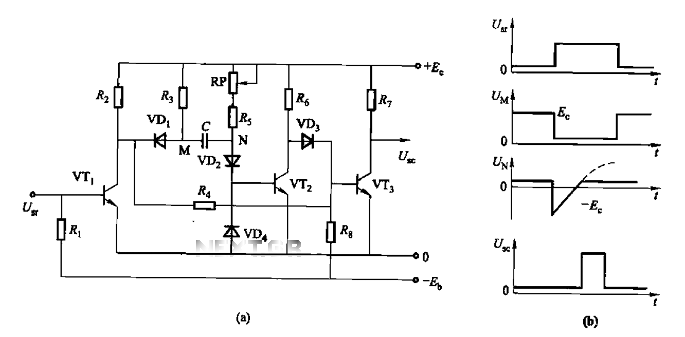
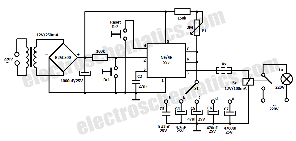
The circuit described is a discharge delay circuit that offers a longer delay compared to a standard rechargeable delay circuit, while also maintaining relatively high accuracy. The schematic diagram illustrates the input and output waveforms. Typically, when there is...
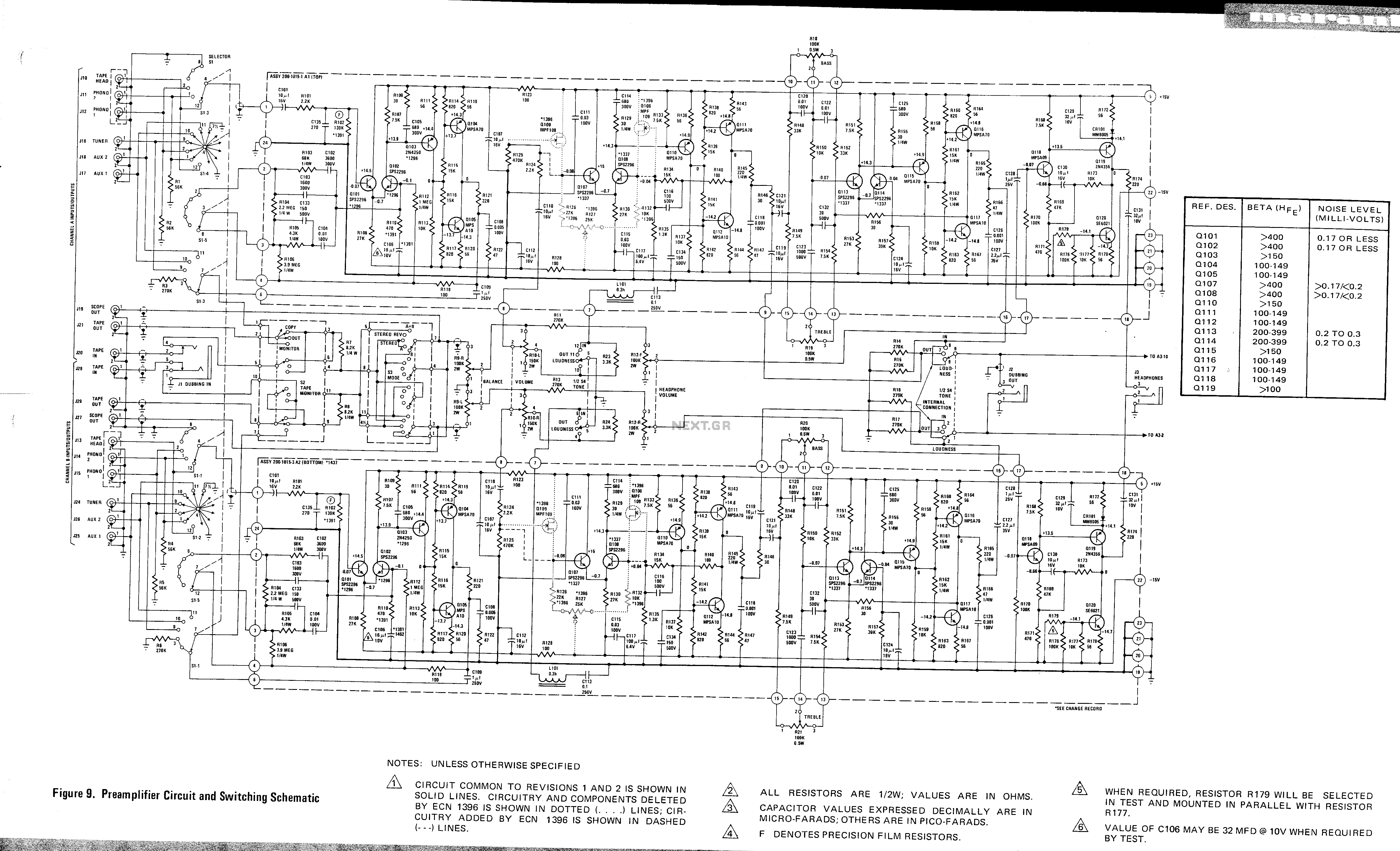
This is a preamplifier circuit and switching schematic for the Marantz Model 33. The Marantz Model 33 preamplifier circuit is designed to amplify low-level audio signals from various sources before sending them to a power amplifier. The schematic typically includes...
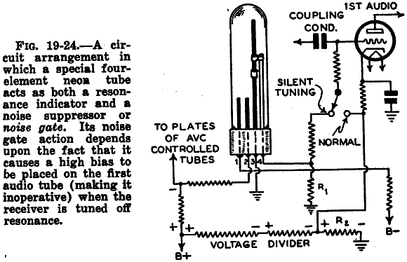
The following two photos illustrate the I/V characteristics of the main anode/cathode current for the Tune-a-Lite 4-element neon tube, which serves as a signal strength meter in certain Fada radios, particularly in the Tune-o-Graph model. A similar 4-terminal Tuneon...
One advantage of a solid-state relay (SSR) over a conventional electromagnetic relay (EMR) is its wear-free operation. The S201S01 from Sharp is a notable example. Solid-state relays (SSRs) are electronic switching devices that use semiconductor components to perform the switching...