
Rf-Field Detector
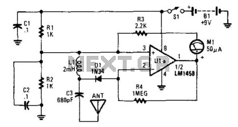
The described circuit functions as a radio frequency (RF) power detector, utilizing a half-wave rectifier to convert RF signals into a usable DC voltage. The half-wave rectifier allows only one half of the AC waveform to pass, effectively rectifying the RF signal. This process is critical for measuring RF power levels, as it translates the high-frequency AC signal into a lower-frequency DC signal.
The operational amplifier (U1A) is configured to amplify the rectified signal. The gain of the op-amp can be set according to the requirements of the application, ensuring that the output voltage is suitable for driving the connected meter (M1). The meter provides a visual indication of the RF power levels detected, allowing users to monitor signal strength easily.
This circuit is capable of detecting RF levels in the milliwatt range, making it suitable for a wide variety of applications, including amateur radio, telecommunications, and RF testing. The frequency range of the detector spans from below the AM broadcast band (approximately 530 kHz) to well above the FM broadcast band (up to several GHz), allowing for versatile usage across different RF signal types.
In terms of design considerations, it is essential to select appropriate components for the rectifier and the op-amp to ensure efficient operation across the desired frequency range. Furthermore, proper filtering may be implemented to reduce noise and improve the accuracy of the power measurement. Overall, this circuit serves as a practical solution for RF power detection, providing essential functionality for various electronic applications. This detector is a half-wave rectifier for RF, which then feeds an op amp. U1A acts as an amplifier, driving meter Ml. Th is circuit can detect mW RF levels from below the AM broadcast band to well above the FM broadcast band. 🔗 External reference
Related Circuits
This circuit gives a low-level output when sufficient lighting is present, functioning as a light detector. It can issue a command to turn on lights when darkness falls. Its output is compatible with TTL levels, providing a low logic...
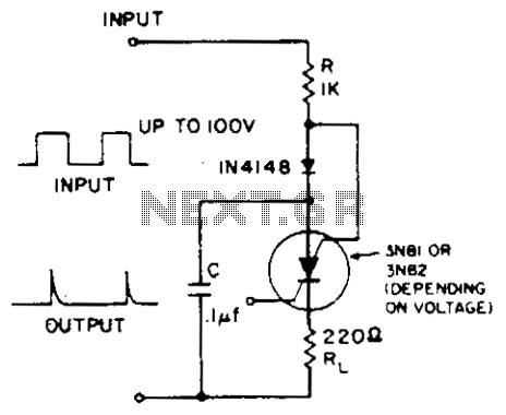
A positive-going input charges capacitor C through the IN4148 diode and resistor R. The diode ensures that the silicon-controlled switch (SCS) remains off. A negative-going input provides anode-gate current, which triggers the SCS, allowing capacitor C to discharge through...
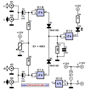
This lie detector circuit diagram provides two readings: one for challenging questions directed at the subject and another to display the subject's emotional state in general. The emotional states are detected not only by heart rate variations and perspiration...
This audio peak detector enables the monitoring of a pair of stereo channels using a single LED. The circuitry employed for both the left and right channels is identical. The audio peak detector circuit is designed to provide a visual...
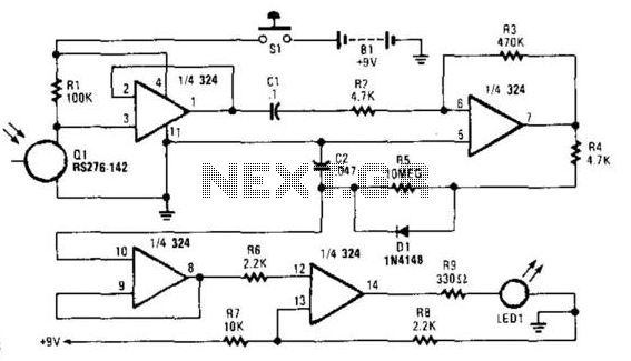
This circuit is useful for checking TV remote controls, IR-based alarm systems, and IR sources. It activates LED1 for two seconds in the presence of IR light pulses. U1A functions as a voltage follower for detector Q1. Capacitor C1...
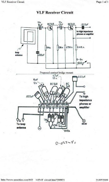
Low frequencies predominantly cover Earth's atmosphere. This range of frequencies can be produced by various unknown and unusual sources. A Very Low Frequency (VLF) sensor equipment can be developed to detect these frequencies for investigating the intriguing secrets hidden...