
Photo-Event Timer

The circuit described involves several components that work together to create a timing system with specific operational modes. The switch S2 serves as the primary control element, initiating the timing sequence. The functionality of S2 is complemented by switch S5, which determines the conditions under which the timer stops—either a transition from light to dark or from dark to light.
S3 introduces an alternative mode of operation, allowing the circuit to function without the need for a latch. This direct operating mode can simplify the timing process, enabling immediate response to S2's activation.
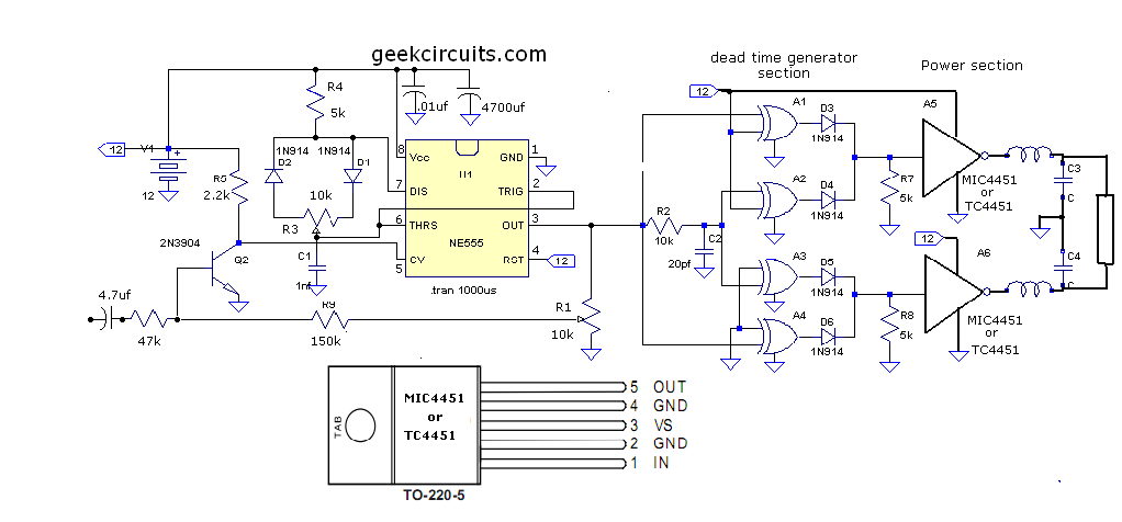
Timing pulses are generated by integrated circuits IC3 and IC4, which can be configured to provide either 0.1-second or 1-second intervals. This flexibility in timing pulse generation allows for various applications depending on the requirements of the overall system.
IC7 is responsible for driving a time display counter, which operates at a voltage of 12 Vdc. This counter is designed to be energy-efficient, drawing less than 200 mA, making it suitable for battery-operated or low-power applications. The design considerations for IC7 ensure that the display remains functional without excessive power consumption, contributing to the overall efficiency of the timing circuit.
This combination of components and their specific roles creates a versatile timing system that can be adapted for different uses, whether in industrial applications, consumer electronics, or educational projects. The careful selection of components and their configurations allows for reliable operation under varying conditions. S2 is used to initiate timing. A light-to-dark or dark-to-light transition stops this timer, depending on the setting of S5. S3 offers a direct operating mode, rather than through the latch. IC3 and IC4 supply 0.1- or 1-second timing pulses. IC7 drives a time display counter, a 12-Vdc unit that draws less than 200 mA.
Related Circuits
This document presents an improvised circuit model designed to eliminate unwanted DC offset voltage from the output, which affects previously discussed circuits. All prior circuits were intended as low-power Class D amplifier sources suitable for driving headphones through a...
A switched timer for intervals of 5 to 30 minutes incremented in 5 minute steps. Simple to build, simple to make, nothing too complicated here. However, you must use the CMOS type 555 timer designated the 7555; a normal...
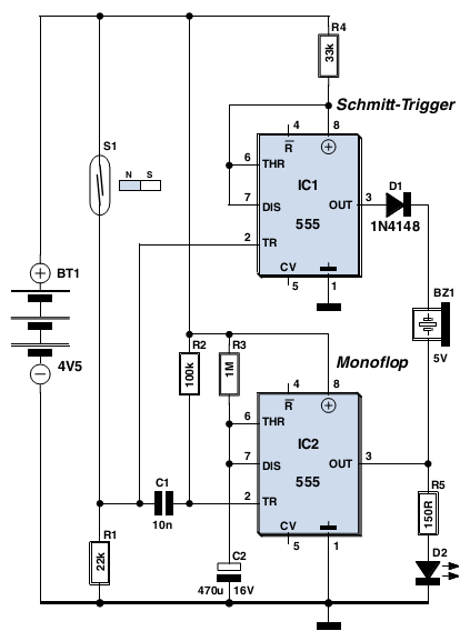
This circuit detects when a window is open (it can also be used with a door), indicates that the window is open by means of a red LED or a blinking LED, and emits a loud acoustic signal from...
This circuit is designed to power a lamp or other appliance for a specified duration of 30 minutes, after which it automatically turns off. It is particularly useful for nighttime reading, as it can turn off a bedside lamp...
The 555 timer is a versatile component that can be utilized as a timer and configured to produce a specific frequency. In Part II of Electronic Project I, a circuit was created to make an LED flash. This time,...
These two circuits are multi-range timers that offer periods of up to 24 hours and beyond. Both circuits are fundamentally similar, with the key distinction being that Version 1 energizes the relay when the time expires, while Version 2...