
5 to 30 Minute Timer
Timing = 1.1 C1 x R1
Note that R1 has a value of 8.2M with S3 at position "a" and 49.2M at position "f".
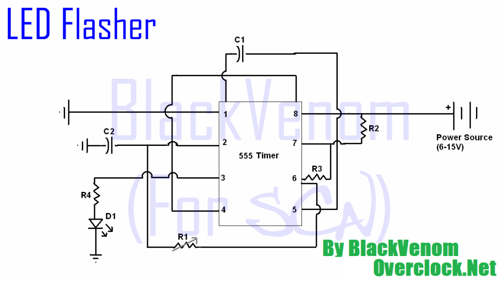
The circuit described is a switched timer utilizing the CMOS 7555 timer IC, which is specifically chosen for its low power consumption and enhanced performance characteristics compared to the standard 555 timer. This timer is designed to provide adjustable timing intervals ranging from 5 to 30 minutes, with the increments set at 5-minute steps.
The primary components of this circuit include the 7555 timer IC, a low-leakage capacitor (C1), and a variable resistor network controlled by Switch 3 (S3). The timing interval is determined by the equation:
Timing = 1.1 * C1 * R1
In this equation, C1 represents the capacitance in farads, and R1 represents the resistance in ohms. The choice of a Tantalum Bead capacitor is critical due to its low leakage properties, which ensures that the timing accuracy is maintained over extended periods.
The resistance value of R1 is adjustable via S3, which can be set to different positions to provide various resistance values. At position "a", R1 is set to 8.2MΩ, while at position "f", it is adjusted to 49.2MΩ. This range allows for fine-tuning of the timing interval to achieve the desired timing output.
The circuit operates by charging the capacitor C1 through the resistor R1. The time it takes for the capacitor to charge to a specific threshold voltage determines the timing interval. When the timer is activated, the output will remain high for the duration calculated by the aforementioned equation before reverting to a low state, effectively creating a timed output pulse.
The simplicity of the circuit design makes it accessible for various applications, including timing relays, delay circuits, or any scenario where a precise timing interval is required. Proper attention must be paid to the selection of components, particularly the use of the CMOS 7555 timer and the low-leakage capacitor, to ensure reliable operation and accurate timing performance.A switched timer for intervals of 5 to 30 minutes incremented in 5 minute steps. Simple to build, simple to make, nothing too complicated here. However you must use the CMOS type 555 timer designated the 7555, a normal 555 timer will not work here due to the resistor values. Also a low leakage type capacitor must be used for C1, and I would strongly suggest a Tantalum Bead type.
Switch 3 adds an extra resistor in series to the timing chain with each rotation, the timing period us defined as :- Timing = 1.1 C1 x R1 Note that R1 has a value of 8.2M with S3 at position "a" and 49.2M at position "f". This 🔗 External reference
Related Circuits
All of the components in this list are generally available through RadioShack for less than $20. It is highly recommended to use a breadboard for assembly, as mistakes are common for first-time builders, and soldering can complicate troubleshooting. This...

This 555 timer circuit temperature monitoring system project can monitor temperature at up to four points. The system allows for the selection of whether the alarm should be triggered when the temperature increases or decreases, depending on the resistance...
This mini metronome provides a linearly scaled output with a range of 40 to 208 beats per minute. The transistors Q1 and Q2 facilitate the linear frequency variation of IC1. The described mini metronome circuit utilizes an integrated circuit (IC1)...
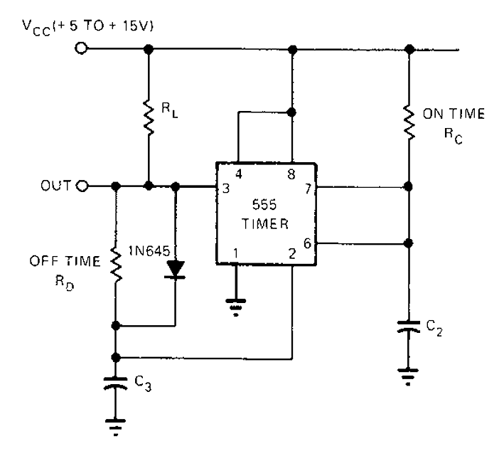
The 555 timer circuit has unsteady open and closing times that are independent of one another. One time constant is given by 1.1RcC2, while another time constant is defined as 1.1RcC3. The free-running period is the sum of these...
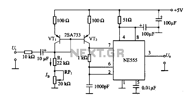
The circuit consists of a NE555 timer and a frequency modulation circuit that modifies the self-excited multivibrator NE555 by adjusting the charging current for frequency modulation. The components VT1 and VT2 form a current mirror circuit, which generates a...
This circuit deactivates an amplifier or any connected device when a low-level audio signal at its input is absent for at least 15 minutes. By pressing P1, the device is powered on, supplying power to any appliance connected to...
Warning: include(partials/cookie-banner.php): Failed to open stream: Permission denied in /var/www/html/nextgr/view-circuit.php on line 713
Warning: include(): Failed opening 'partials/cookie-banner.php' for inclusion (include_path='.:/usr/share/php') in /var/www/html/nextgr/view-circuit.php on line 713