
555 Timer with a Speaker
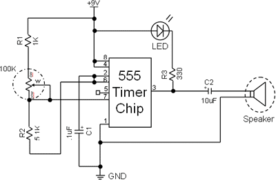
The circuit utilizing the 555 timer is designed to create an audio signal that can be modulated by adjusting the potentiometer. The 555 timer operates in astable mode, generating a continuous square wave output. The frequency of this output is determined by the values of the resistors and capacitors connected to the timer. In this setup, the potentiometer serves as a variable resistor, allowing for frequency modulation.
The power supply for the circuit is provided by a 9-volt battery, which is connected to the power and ground pins of the 555 timer. The LED serves as a visual indicator of the timer's operation, while the speaker converts the electrical signals into sound. The capacitor plays a crucial role in defining the timing intervals and frequency of the output signal.
The connections made to the potentiometer are critical for its functionality. The wiper (middle pin) adjusts the resistance in the circuit, affecting the charging and discharging times of the capacitor and thereby altering the frequency of the output signal. The use of different colored wires for connections helps in maintaining clarity and organization in the circuit layout, which is essential for troubleshooting.
In summary, this circuit effectively demonstrates the principles of frequency generation using a 555 timer, while also providing an engaging way to learn about electronic components and their interactions. Proper assembly and careful attention to detail are essential for the successful operation of the circuit.555 Timers are very fun to encounter and experiment with. They can be used as a timer and can be set to a certain frequency. In Part II of Electronic Project I, we created a circuit that would get an LED to flash. This time we are going to add a speaker so that we can hear the frequency that is being emitted. · I did not put an estimate next to t his one because it can vary depending on the quality and how much you are willing to invest in a speaker. Speakers can be bought or purloined from an old boombox or stereo that you don`t need or want. For a refresher on how to insert chips into board, see Part V. Next, make power and ground connections to the chip as shown to the right. It is typically a good habit to have red wire be exclusively power and black exclusively ground. If problems arise, you can easily pick out where power and ground is traveling. Next, add the potentiometer and LED to the board (as pictured to the left). These are the next important components in this circuit. Make sure to place the potentiometer so that the pins are in different rows; see Part IV for a refresher on how to plug potentiometers into the board.
Using a different color than red or black, connect pin 2 to pin 6 (I used yellow wire). The 1 F capacitor was inserted (as can be seen to the left). This capacitor is of ceramic type and so it doesn`t matter which lead is connected to ground or the chip. If you have a polarized capacitor, make sure that the "+" side is toward the chip or that the " " side is toward ground.
In the image to the right, I added a grey wire to a resistor and connected the other side of the resistor to the LED. Next I added a wire connecting the "ccw" and "w" pins on the potentiometer (the minuscule wire is circled in orange).
I also connected the middle pin of the potentiometer to pin 7 via a green wire and also through the 5. 1k © resistor to pin 2 via a purple wire. The 1k © is connected to the "cw" pin of the potentiometer and power. So what are "ccw", "w", and "cw" These are counter-clockwise, wiper, and clockwise respectively. How do you distinguish pins The middle pin is always the wiper. The outer pins are defined by the manufacturer and there is no set way to distinguish them other than by looking at the part description.
The outer pins can be connected in the orientation in the schematic without regard to which is the counter-clockwise pin and which is the clockwise pin. The final step before trying this out is to add the capacitor and speaker (shown below). Be sure that the "-" side lead is attached to the speaker. Make sure also that the speaker is grounded. The left image shows the pins of the speaker as it connects directly to ground. Now try plugging power from the 9 volt battery into the board. If the LED seems to stay lit instead of blinking, that is okay. What the LED is really doing (in most cases) is blinking so fast that it seems to just stay lit. You should hear a sound from the speaker. As you turn the potentiometer, it should change in frequency. Congratulations to those who accomplished this feat. If yours isn`t working right away, there is a basic checklist that you should walk through before becoming too discouraged.
Chances are it is only a minor issue. o Make certain that not only the components are wired correctly (it is easy to be just one row off), but also that they are inserted correctly. Capacitors and LEDs are likely culprits of not being inserted correctly as they are polarized. o Does something smell like it is burning Is there a black area on a component If this is the case, swap out the component and double check the value and the wiring.
Something was not wired correctly to make the component break. This concludes the Electronic Project I that uses the 555 timer to make simple circuits. Tune in in two weeks when we use operational amplifiers to make filters for music. 🔗 External reference
Related Circuits
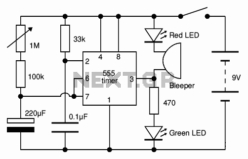
The Adjustable Timer circuit initiates timing upon activation. A green LED illuminates to indicate that timing is in progress. Once the designated time period elapses, the green LED turns off, the red LED activates, and an audible bleeper sounds....
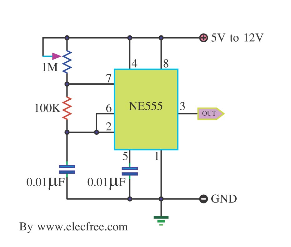
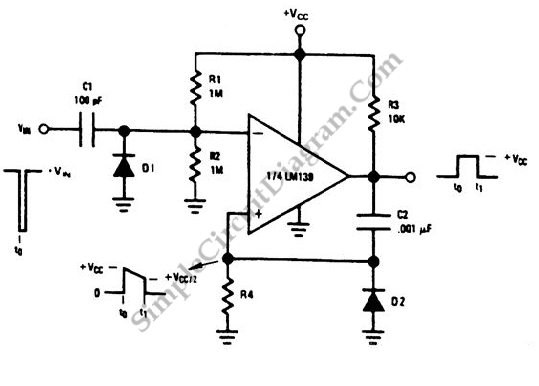
This is a simple pulse generator circuit or standard astable oscillator circuit for the IC 555 timer, NE555N IC. The astable oscillator circuit utilizing the NE555 timer IC serves as a versatile pulse generator, producing a continuous square wave...
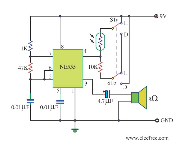
This circuit detects light and provides a voice warning. It responds to changes in light conditions, becoming active based on the position of switch S1. The circuit utilizes a light-dependent resistor (LDR) to sense ambient light levels. When the light...
A one-shot multivibrator circuit, commonly referred to as a monostable multivibrator or timer, is designed to generate a pulse strobe of fixed duration in response to an input trigger. The one-shot multivibrator is a fundamental circuit used in various electronic...
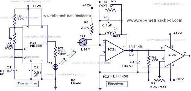
All components used in the Moving Sensor/Detector Schematic Diagram utilize the IC NE555 and the Phototransistor L14F. The primary component in this circuit is the IC NE555, along with an IR LED, the Phototransistor L14F, and the IC LM1458....
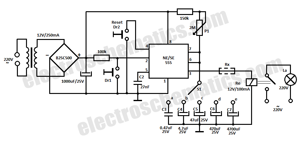
This time delay relay circuit is constructed using the NE/SE555 integrated circuit, manufactured by Intersil, which features a precision timer. The circuit exhibits stability against temperature variations. The NE/SE555 integrated circuit is a versatile timer used in various applications, including...