
Photoelectric Smoke Detector

The photoelectric smoke detector circuit operates based on the principle of light scattering. In this design, an LED emits light that is directed towards the two LDRs positioned in the detection chamber. Under normal conditions, the light from the LED does not reach the LDRs as it is not scattered. However, when smoke particles enter the chamber, they scatter the light emitted by the LED, causing a change in the light intensity detected by the LDRs.
The LM1801 IC plays a crucial role in processing the signals from the LDRs. It is designed to compare the voltage levels generated by the LDRs against a predefined threshold. When the smoke presence alters the light intensity, the voltage across the LDRs changes, triggering the LM1801 to activate an alarm. This alarm can be implemented using a piezo buzzer or any other suitable sound-generating device.
In terms of circuit components, the LED should be selected for its appropriate wavelength to ensure effective scattering by smoke particles. The LDRs must be chosen based on their sensitivity to the light emitted by the LED, ensuring they can detect even subtle changes in light intensity. Additional components such as resistors and capacitors may be included to stabilize the circuit and filter out noise, enhancing the reliability of the smoke detection.
Power supply considerations are also important; the circuit should be designed to operate efficiently with a suitable voltage source, ensuring that the LM1801 IC and the LED function optimally. Overall, this smoke detector circuit is a practical application of photoelectric principles, providing an essential safety feature for various environments.This photoelectric smoke detector circuit uses one LED and 2 LDRs to detect the smoke and sound an alarm. The LM1801 IC is the best choice for this circuit.. 🔗 External reference
Related Circuits
This project has not been called a GOLD detector as this name has been left for the more complex detectors that actually discriminate between gold and other metals. There is an enormous difference between detecting gold and ordinary metals...
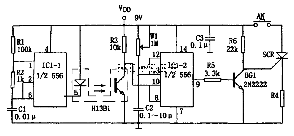
The circuit shown is a photoelectron pulse missing detection circuit. It includes an optoelectronic slotted switch H13B1, a dual time base circuit using a 556 timer IC, and several RC components that form a one-shot multivibrator. The design incorporates...
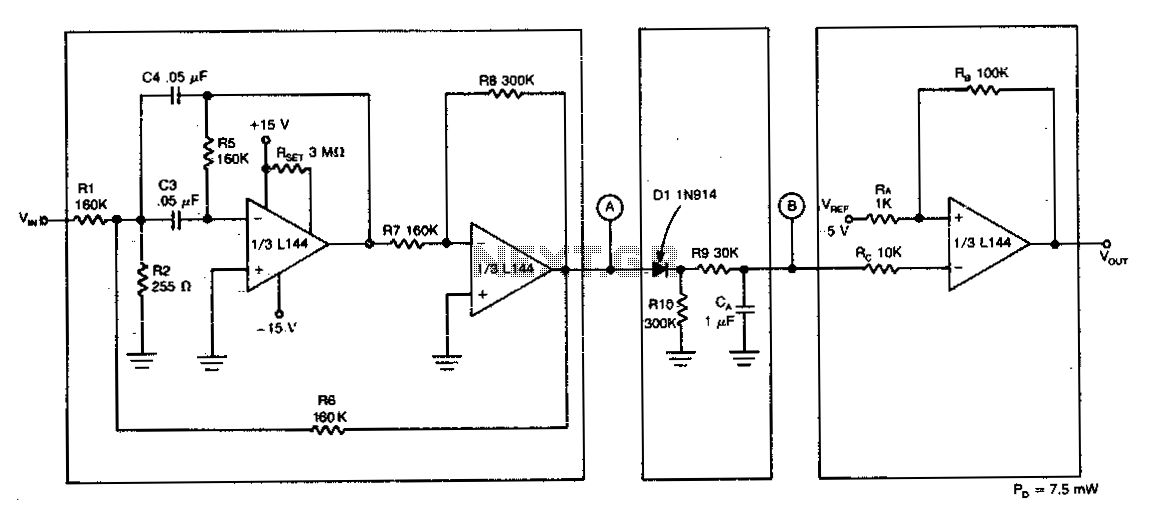
The detector circuit consists of a two-amplifier multiple feedback bandpass filter followed by an AC-to-DC detector section and a Schmitt Trigger. The bandpass filter, with a quality factor (Q) greater than 100, allows only 500 Hz inputs, which are...

The motion sensor circuit depicted in Figure 1 operates when a 12-volt power supply is applied to the input point. The motion sensor circuit is designed to detect movement and trigger a response based on the presence of motion...
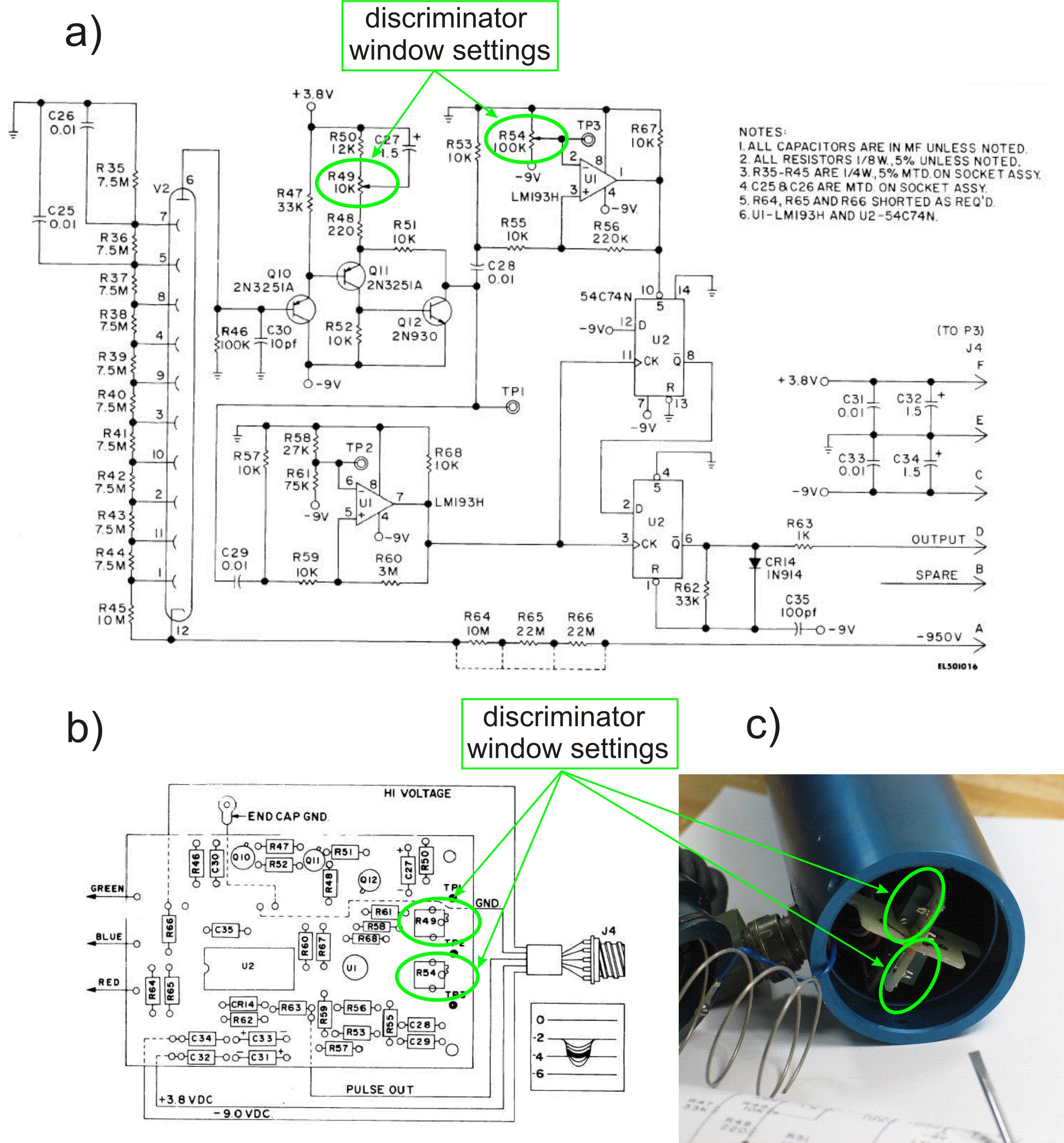
This PDF file presents the schematic diagram of a custom-built circuit designed to drive the PDR-56 probe. A JKL BXA-12579 inverter, typically used for powering cold-cathode fluorescent lamps, serves as the high-voltage power supply. The BXA-12579 generates 1,500 VAC...
A single-chip metal detector with a detection range of a few inches. This device is useful for identifying nails or screws in walls and floors, as well as locating buried mains cables. The core of the metal detector circuit...