
556 photoelectron pulse detectors omission
The photoelectron pulse missing detection circuit is engineered to reliably detect interruptions in light paths, making it suitable for applications where monitoring of light signals is critical. The H13B1 optoelectronic switch serves as a sensitive light sensor, responding to the presence or absence of light within its defined slot. The dual time base circuit, utilizing the 556 timer IC, is pivotal for timing and pulse generation, enabling precise control over the detection and response mechanisms.
The integration of RC components in the one-shot multivibrator configuration allows for flexible timing adjustments. By modifying the resistance values of R1 and R2 or changing the capacitance of C2, the user can calibrate the circuit to accommodate various environmental conditions or specific application requirements. The SCR (Silicon Controlled Rectifier) acts as a switch that can handle high power loads, ensuring that the output response is robust enough to activate alarms or control other devices in response to light interruptions.
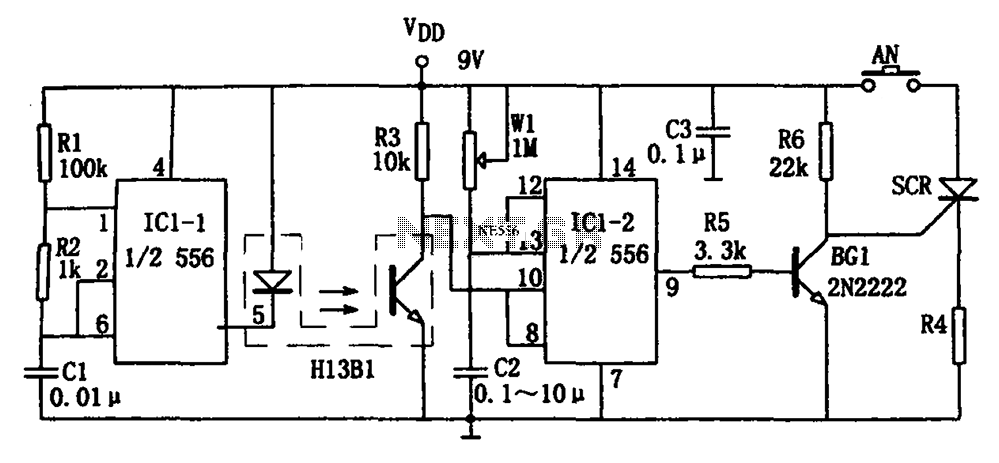
The design's high duty cycle of 99% ensures that the H13B1 luminous tube remains illuminated most of the time, providing a clear visual indication of the circuit's operational status. This feature is particularly useful in environments where immediate visibility of the circuit's performance is necessary. Overall, the circuit is a sophisticated solution for detecting light interruptions, offering adjustable timing capabilities and reliable output responses for a variety of applications. As shown in FIG photoelectron pulse missing detection circuit. The detector consists of optoelectronics slotted switch H13B1, dual time base circuit 556 with some RC components constituting the one-shot multivibrator and other components. It opened a few millimeters slots between the arc tube and the photosensitive optoelectronic switch H13B1 tube inside. When the external light blocking object into its slot, H13B1 internal photodiode beam path is cut off due to a high-impedance so IC1-2 (1/2 556) pulse signal detector due to lack of a reset signal and output high into the temporary steady state, transient stability corresponding time td 1.1RwlC2, and adjust W1 can be changed td.
If the signal interruption longer than the temporary stabilization time of magic, the IC1-2 reset, active low output enable pin BG1 end, SCR SCR conduction, so that the corresponding load RL is energized, or the power supply circuit is disconnected, or issue alarm signal. Multivibrator IC1-1 (1/2 556) and R1, R2, C1 and other components, the oscillation frequency of f 1.44/(R1 + 2R2) C1, the icon parameter corresponding oscillation signal frequency of approximately 2.5kHz 99% duty cycle, high duty cycle of the pulse signal driving the H13B1 luminous tube lighting.
Related Circuits
This circuit operates a LED in pulsing mode, i.e. the LED goes from off state, lights up gradually, then dims gradually, etc. This operation mode is obtained by a triangular wave generator formed by two op-amps contained in a...

The solenoid operates with pulse action, receiving a brief surge of five to six times its rated voltage, followed by a holding voltage that is less than half of its rated voltage. This method significantly reduces application time, and...
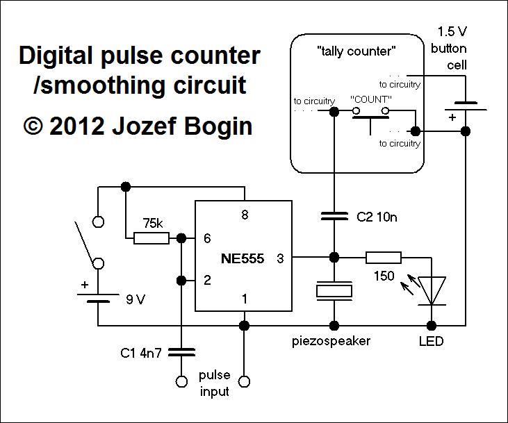
This is a simple yet versatile pulse counting and smoothing integrator circuit featuring an NE555 timer as the waveform shaper and a small LCD display for output. Originally designed for counting pulses from Geiger counters, it includes a piezo...
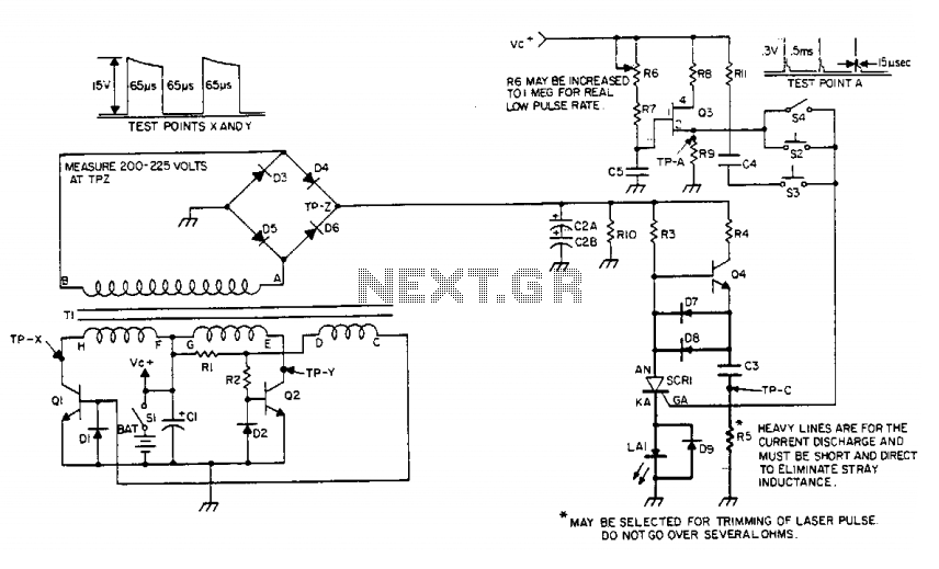
The device generates an adjustable frequency of low to medium powered infrared (IR) pulses of invisible energy and must be handled with care. The portable battery pack is stepped up to 200 to 300 volts by the inverter circuit,...
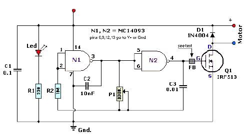
A quad 2-input NAND Schmitt trigger circuit can be designed using the MC14093 CMOS type IC, which serves as a simple pulse width modulation (PWM) controller electronic project. This PWM controller is straightforward and requires only a few external...
The circuit presented on this page attempts to be an interface to convert pulses such as provided by a Basic Stamp or R/C receiver to a dual PWM (Pulse Width Modulation) signal required by an H-bridge. The simplest circuit...