
Photomultiplier output-gating circuit

The circuit described is designed to observe light pulses generated from a thick specimen illuminated by a laser pulse through transillumination. The system employs a laser source that emits pulses at a frequency of 500 Hz. The initial light pulses produced by the laser are weak and require amplification to be effectively processed. A Video Amplifier LM733 is used for this amplification, ensuring that the signal is strong enough for subsequent processing.
To manage the signal effectively, a comparator LM710 is utilized. It is configured with a reference level set at 1 V, which serves as a threshold for triggering the next stage of the circuit. The output from the comparator generates trigger pulses that are fed into a monostable multivibrator, specifically the 74121 model. This component is critical in generating a defined output pulse in response to the trigger input, which is essential for timing and synchronization in the overall system.
The component values specified in the circuit are crucial for determining the behavior of the monostable multivibrator. The resistors and capacitors, R1 = 33 kΩ, C1 = 22 pF for the first stage and R2 = 33 kΩ, C2 = 68 nF for the second stage, are selected to ensure that the pulse width (t_w) generated by the monostable multivibrator is appropriate for the application. The pulse width can be calculated using the formula t_w = 0.7 RC, highlighting the relationship between resistance, capacitance, and the resulting pulse duration.
Additionally, R3 and C3 form a high-pass filter in the circuit. This filter serves to eliminate low-frequency noise and allows only the higher frequency components of the signal to pass through, further refining the output signal. The design emphasizes the use of low-cost components, which is advantageous for practical applications where budget constraints are a consideration, while still achieving moderate response times necessary for effective pulse extraction. This approach ensures a balance between performance and cost, making the circuit suitable for various experimental setups in optical and photonic applications.The application involves observing the light pulse emerging from a thick specimen after transillumination by a laser pulse. Pulses derived from the laser source are amplified using a Video Amplifier LM733. The reference level is set to 1 V in the comparator LM 710, to provide the necessary trigger pulses for the monostable multivibrator 74121.
The laser pulses have a repetition frequency of 500 Hz and suitable values are as below: Rl = 33 k ohm, Cl = 22 pF R2 = 33 k ohm, C2 = 68 nF. The pulse width for each monostable is approximately given by tw = 0.7 RC. R3 and C3 is a high pass filter. The method therefore permits the use of low cost components having moderate response times for extracting the pulse of interest. 🔗 External reference
Related Circuits
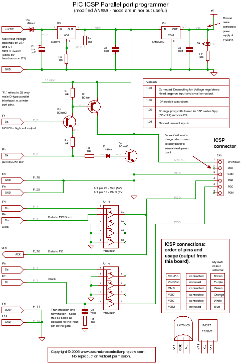
A PIC programmer circuit that operates using long cables from a PC to the programmer. The PIC programmer circuit is designed to facilitate the programming of PIC microcontrollers via a connection to a personal computer (PC) using extended cabling. This...
This is an intercom circuit that utilizes the LM380 as the audio amplifier and two transistors for the microphone preamplifier. The sound quality is sufficiently good while maintaining a low construction cost. The circuit comprises two identical intercom units,...
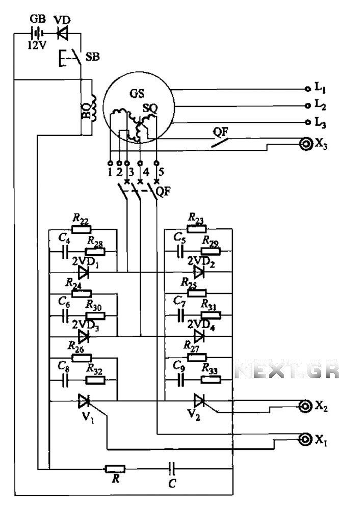
The setup is connected to separate stator windings of a harmonic generator, which leads to a thyristor rectifier supply for the third harmonic voltage, positioned after the motor field. The output voltage varies with changes in the winding harmonics...
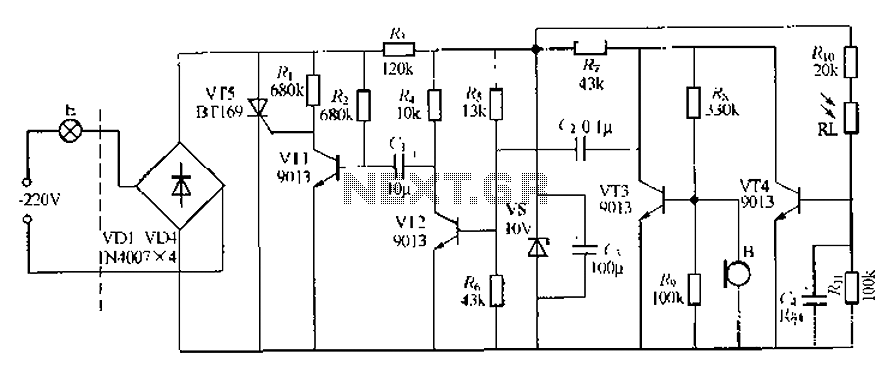
This circuit describes a sound and light control delay system for a walkway stairs light switch. It involves various components including 220V AC electric bulbs, diodes (VD1-VD4), and resistors. The circuit utilizes a rectifier regulator to stabilize the voltage...

The circuit depicted in Figure 3-189 includes various components such as switch SA, closing button SBi, trip button SBz, de-excitation switch Yaa, and off trip coil YR3. The excitation switch contacts are represented by QF3, which serves as a...
A simple audio compressor is designed using the SSM2165 integrated circuit (IC). There is limited explanation available regarding the schematic of this compressor circuit; however, special attention should be given to the capacitor used. The audio compressor circuit utilizing the...
Warning: include(partials/cookie-banner.php): Failed to open stream: Permission denied in /var/www/html/nextgr/view-circuit.php on line 713
Warning: include(): Failed opening 'partials/cookie-banner.php' for inclusion (include_path='.:/usr/share/php') in /var/www/html/nextgr/view-circuit.php on line 713