
Discrete components sound and light control stairs delay switch circuit 4

The sound and light control delay circuit is designed to enhance safety and convenience in illuminated pathways, particularly on stairs. The primary components include a 220V AC power source, light bulbs, diodes (VD1 to VD4), resistors (R1, R2, etc.), and multiple transistors (VT1 to VT5). The circuit's operation hinges on the interaction between these components to manage the lighting based on ambient sound levels.
The circuit begins with the AC power supply, which feeds into the light bulbs through a series of components that include diodes for rectification. The diodes (VD1-VD4) rectify the AC voltage, allowing it to be usable for the rest of the circuit. The rectified voltage is then stabilized by a regulator circuit, ensuring consistent voltage levels for the transistors to operate effectively.
In daylight conditions, the circuit maintains low resistance, enabling transistor VT4 to conduct. This condition results in a low collector potential at VT3, preventing it from turning on. Consequently, transistors VT1 and VT2 are off, which keeps the light bulbs off as well. The circuit is designed to remain in this state until an acoustic signal is detected.
When a sound is picked up by the microphone, it triggers the amplification process through VT3, which boosts the acoustic signal. This amplified signal subsequently activates VT2 and VT1, allowing current to flow through VT5, which powers the light bulbs. The illumination occurs as long as the acoustic signal is present.
Once the sound fades, the circuit begins its delay sequence. The resistors (R) control the timing of this delay, allowing the circuit to remain active for a predetermined period before turning off the light. As the sound dissipates, VT2 enters a recovery state, leading to the deactivation of VT1 and, consequently, the light bulbs. The circuit is designed to ensure that the lights remain illuminated for a short duration even after the sound ends, thereby enhancing visibility during transitions.
The overall timing of the delay can be adjusted by modifying the resistor values in the circuit, allowing for customization based on specific needs. This circuit is particularly useful in environments where hands-free operation of lighting is beneficial, such as in residential staircases or public walkways. The combination of sound detection and light control provides an efficient and user-friendly solution for managing illumination in various settings.Another setback law sound and light control delay walkway stairs light switch circuit. VDl - VI) 1, off + VT5 constitute Ji - Ji Guan road called Route VTl- VT4 control with ot her components of the composition, 220V AC electric bulbs by Chan E, diode VDI- VD4, R; 5 vs simple composition of the ohmic drop n, rectifier regulator circuit, in (1 Liduan available by 1 () ,. abysmal stabilized voltage power supply control back to the hoof. RI. VT4 composition and light control circuit, daytime s. exhibits low resistance, VT4 conducting, the audio amplification tube VT3 collector potential clamped at low Iu half, so VT3 can not be made small.
in this case VT2, VTI are off ten saturated conduction plate-shaped crystal state tube Vlj f] - pole trigger H {, breaking the curse in blogs, not bright lights F to the night late, Rl, show a high resistance, VT4 off, VT3 lifting of the blockade. If at this time to pick up the microphone B acoustic signal VT3 disadvantages to enlarge coupled by C.
v linden small group 2, the peak signal will sound green VTZ, VT1 have entered the end zone, VT5 by R, stopping to get trigger current opened, the lamp is powered F light. when stored VT2 into the end zone .c. by R. charge when sound accounting disappeared, VT2 conduction recovery concept, (- prompt end of JF maple ask a ground potential, it will also VT1 base t pull the ground, so Vl, l still remains off -state, electric lights are still bright.
when (1 through R, R, R after discharged, VT1 recovery guide .VT5 quiet city lost to f J shake trigger current, when the AC zero crossing, namely inflammation off, the lamp F was extinguished. Bong circuit delay time to soil (values to determine R, 1., and according to need eight whole.
Related Circuits
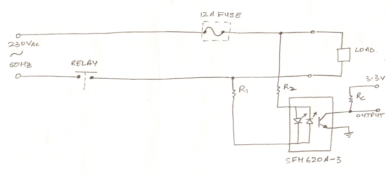
The circuit utilizes an optocoupler (MOC3021) to detect the On/Off state of an electrical appliance using a microcontroller (ATmega16L). The mains supply specifications are 230V, 50Hz. The design aims to determine whether the load is active or inactive. The...
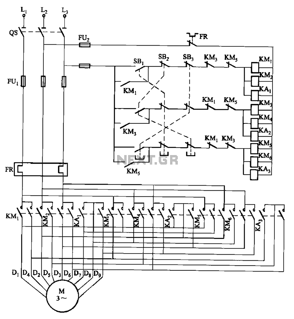
The circuit depicted in Figure 3-115 utilizes contactors and double buttons, allowing for speed conversion without the need to press the stop button. The buttons SBi, SBz, and SB3 correspond to high, medium, and low-speed operation, respectively. This circuit design...
When the water level is low, the wires in the tank are open-circuited, and the 180K resistor pulls the switch low, resulting in the switch opening and the LEDs turning OFF. As the water begins to fill the tank,...
This power supply was designed for use with the Simple hybrid amplifier published elsewhere in this issue. It is suitable for various applications as well. A cascade generator is utilized for the 170 V output, a switch-mode supply provides...
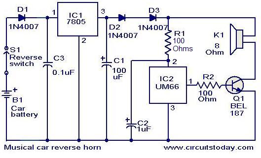
This circuit is designed to produce a musical horn whenever a car is in reverse gear. It utilizes two integrated circuits (ICs) for its operation: a voltage regulator (7805, referred to as IC1) and a musical tone generator (UM66,...

This is a design circuit diagram of a versatile FM transmitter. This circuit does not include a coil and is simple and easy to assemble. It operates based on gate logic concepts. The circuit features a buffer gate N1...