
Solenoid control circuit
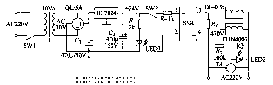
An AC solenoid-driven control circuit employing a solid-state relay (SSR) operates efficiently for industrial applications, particularly in ironworks and foundries. The circuit begins with a 220V AC power supply, which is transformed to a lower voltage of 30V AC using transformer T. This step-down voltage is crucial for safe operation and compatibility with the subsequent components.
The circuit features a rectifier that converts the AC voltage to a pulsating DC voltage. This is followed by capacitor C, which smoothens the rectified voltage, providing a more stable DC output. The filter regulator IC7824 plays a pivotal role in this setup, regulating the voltage to a precise +24V, which is necessary for the solenoid control circuit to function correctly.
The circuit is equipped with a power indicator LED1 (red), which provides visual feedback that the circuit is powered and operational. This is particularly important in industrial settings where multiple systems may be in operation.
The electromagnetic crane, capable of lifting up to 0.5 tons of pig iron, is controlled through the operation of switches SW1 and SW2. When SW1 is closed, the circuit is energized, allowing the operator to control the crane's movements. The crane's electromagnet is activated when switch SW2 is closed, which energizes solid-state relay SSR1. This relay is designed for high efficiency and reliability, ensuring that the solenoid receives the necessary power to lift the iron.
As the crane lifts the warm iron, it transports it to the cupola, a furnace used for melting iron. The circuit includes safety features, such as the activation of LED2 (green) to indicate that the operation is in progress and an alarm (DL) that sounds to alert personnel of the ongoing operation, emphasizing the importance of safety in industrial environments.
Upon releasing the switch SW2, the circuit disconnects, allowing the pig iron to fall into the furnace. This process is seamless and ensures that operations can be conducted safely and efficiently, highlighting the importance of precise control in industrial automation systems. The design and implementation of this circuit demonstrate a robust approach to managing heavy lifting tasks within a foundry setting.AC solenoid driven control with SSR principle is shown in Fig. The switch is closed SW1,220V AC transformer through the transformer T to AC 30V, the QL crossing barrier rectifier; capacitance C. , G filter, regulator IC IC7824 output + 24V supply solenoid control circuit, power indicator LED1 (red) lights up. This circuit is used ironworks, foundry iron with feeding electromagnetic crane (one can lift 0.5t pig iron).
Move motion hoist electromagnetic crane to move raw materials (iron) position, dropped to iron heap. Closes the switch SW2, solid state relay SSR1 eligible for the positive supply terminal is turned, SSR fine the end and feet conduction, solenoid is energized DT absorption of iron. Electric hoist lifting electromagnets. The warm iron raw material to the cupola, disconnect switch SW2, pig iron fall within the furnace, there are lights LED2 (green) indication at work.
And a DL alarm sound, indicating that people pay attention to safety.
Related Circuits
The internal mute circuit and pre-set gain resistors provide a cost-effective design solution. Output power specifications at both 20V and 24V supplies, along with a low external component count, offer significant value to consumer electronic manufacturers for stereo TV...

The circuit depicted in Figure 3-157 is designed for motors with a capacity of no more than 11 kW, requiring precise stopping capabilities. Upon shutdown, contact KMi releases, and the motor stator windings are configured into a three-phase rectifier...
While developing an infrared (IR) extender circuit, a method was needed to measure the relative intensities of different infrared light sources. This circuit utilizes an SFH2030 photodiode as the infrared sensor. A CA3140 MOSFET operational amplifier is employed in...
Most PC enclosures provide only a single LED to indicate hard disk access, with the LED being connected to the motherboard via a two-pin connector. However, this LED only works with IDE drives, and if a SCSI disk controller...
This is the simplest VU meter that can be constructed. It is based on a single integrated circuit. A volume unit (VU) meter, or standard volume indicator, is a device used to display the level of any voltage signal...
The Clock Controller was designed to be an exemplary of using 'C' language to control timer0 interrupt, 7-segment LED and keypad scanning. It provides 1-bit sink current driving output, for driving a relay, opto-triac, say. Many projects requiring 7-segment...
Warning: include(partials/cookie-banner.php): Failed to open stream: Permission denied in /var/www/html/nextgr/view-circuit.php on line 713
Warning: include(): Failed opening 'partials/cookie-banner.php' for inclusion (include_path='.:/usr/share/php') in /var/www/html/nextgr/view-circuit.php on line 713