
PIC CW Temp Circuit
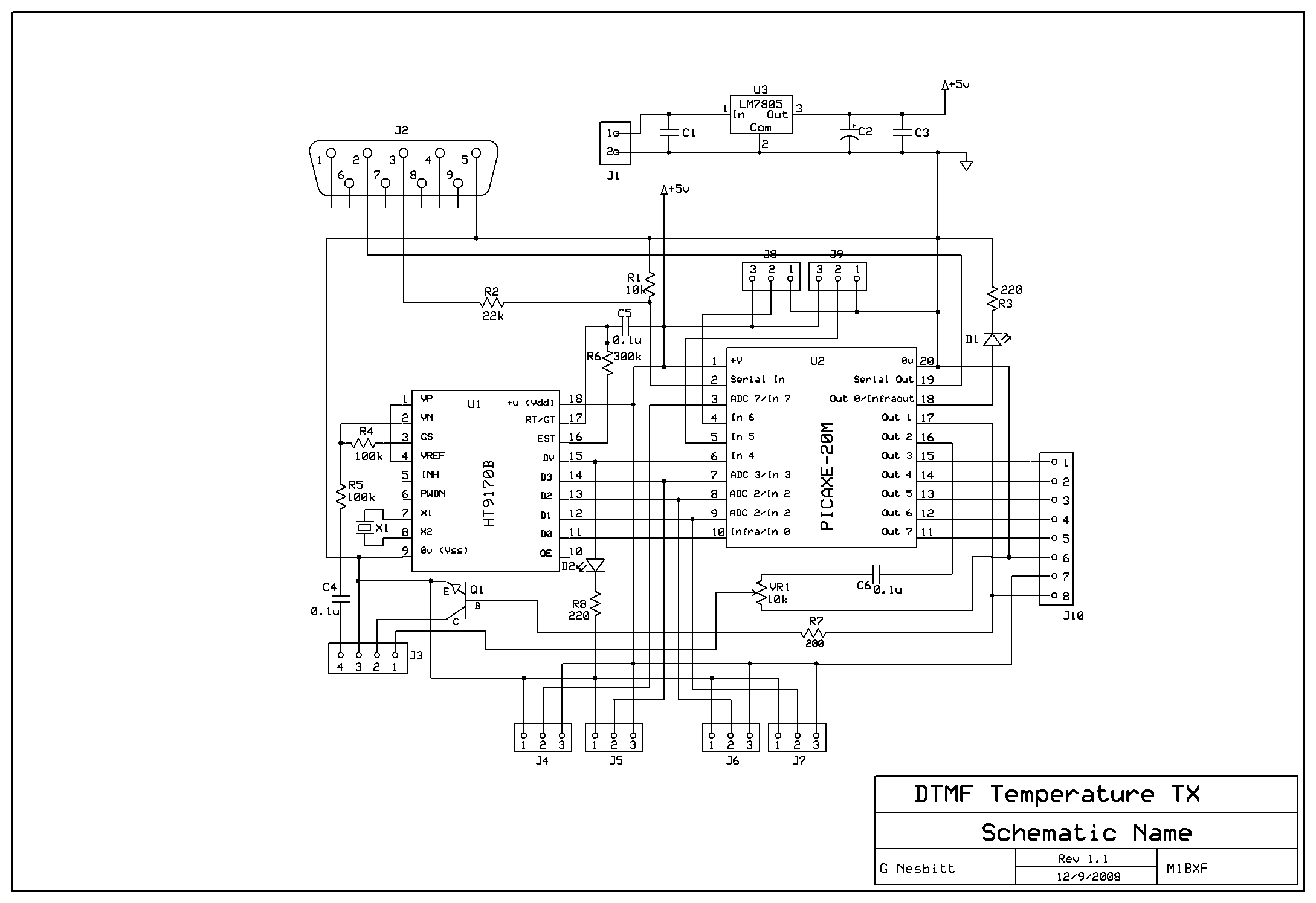
The described system is designed for remote temperature monitoring using a combination of radio communication and DTMF signaling. The HT9170B DTMF decoder acts as the core component for interpreting the DTMF tones transmitted by the user. Upon receiving a valid tone, it generates a corresponding binary output that the PICAXE microcontroller processes to determine the requested action. The integration of the DV pin enhances the efficiency of the system by allowing the PICAXE to respond only when valid data is available, reducing unnecessary processing cycles.
The temperature sensors used in the project can be of various types, such as thermistors or digital temperature sensors, depending on the required accuracy and response time. The choice of sensors should be compatible with the input specifications of the PICAXE microcontroller. The schematic design would typically include power supply arrangements for both the PICAXE and the DTMF decoder, as well as the necessary pull-up or pull-down resistors for the input pins.
The PCB layout must ensure that the traces are appropriately routed to minimize interference and maintain signal integrity, especially in a radio frequency environment. Adequate spacing between components and proper grounding techniques should be employed to enhance the overall performance of the system. Additionally, the code logic should be thoroughly commented to facilitate understanding and further development, particularly for users who may wish to modify or expand upon the existing functionality.
In conclusion, this project exemplifies the use of DTMF signaling for remote temperature monitoring, leveraging the capabilities of the PICAXE microcontroller and the HT9170B DTMF decoder to create an efficient and effective system. The availability of the schematic, PCB layout, and code for download provides a valuable resource for others interested in similar applications.Remotly check the temperature of a few things, in my case the repeater site at GB3PY. A system which used a radio to receive requests for the currenttemperature and send the results back to the user. Requests are by DTMF tones and the response is in CW, mores code. The full design has not been tested, but I`ve managaed to do it with 2 sensors which works fine. This is an ongoing project and after a request from a friend about using PICAXE to decode DTMF I thought I would post details of the project which demonstrates the wayI do it. The PICAXE code, schematic and PCB layout are all available todownload below. The code has afew things worth mentioning in it. When the HT9170B DTMF decoder chip gets a valid DTMF tone it outputs the value in binary (check the datasheet) but DTMF 1 outputs binary 1 or 0001 and DTMF 8 outputs binary 8 or 0100.
Not only this there is a line called DV, pin 15 on the HT9170B which goes high when a valid DTMF tone is decode, this is great cause it is a way to tell the PICAXE it is time to read the input pins. You`ll see this in the code on line 41 if pin4 = 0 then goto start`. Basically I have a pin set in the code, this is between lines 42 and 72 and if the valid pin is entered then we read the temp and respond.
The code below should be enough to read the DTMF value and store is register B0 using just the DTMF chip and PICAXE. so B0 is the actual value of the DTMF key pressed. 🔗 External reference
Related Circuits
The circuit-delay relay for speakers serves as a delay mechanism that prevents the immediate activation of speakers when the amplifier is powered on. This feature is designed to protect the speakers from potential damage caused by sudden power surges....
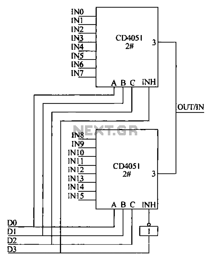
The CD4051 is a single-ended input 8-channel multiplexer that features three channel select inputs (A, B, C) and an inhibit input (INH). The signals at inputs A, B, and C are utilized to control the selection of one of...
The automatic sprinkler controller circuit consists of a +12 V power supply circuit, a light control circuit, and an irrigation control circuit, as illustrated in the accompanying figure. The +12 V power supply circuit includes a knife switch (Q),...
The oscillator that consists of a quartz crystal can be classified into two types: the parallel resonant type crystal oscillator and the series resonant type crystal oscillator. The parallel resonant type crystal oscillator and its AC equivalent circuit are...

A fluorescent starter bimetal can be utilized as a temperature sensing element for thermostatic control. This component consists of a double metal sheet designed for temperature sensing, resulting in a simple circuit that is easy to manufacture, although it...
The power supply has been simplified. Power transformers and rectifiers have been omitted, and some components from the MOSFET voltage regulator circuits have been removed, including 1N5242 zener diodes between the source and gate and 10k resistors in series...