
pic digital clock timer
The clock timer circuit is designed around the PIC16F628 microcontroller, which handles the timekeeping and display functions. The microcontroller interfaces with a 7-segment display to visually represent the time, leveraging a multiplexing technique to drive the display efficiently. The microcontroller's GPIO pins are configured to control the display segments and manage the input from the various switches (RA5, D, E, F, and C).
The timing function relies on a 32.768 kHz crystal oscillator, which is a common choice for timekeeping applications due to its stability and availability. The addition of a 24pF capacitor allows for fine-tuning of the oscillator frequency, which is critical for maintaining accurate time. The correction feature is implemented through software adjustments in the microcontroller, which periodically adds an extra second based on the user-defined settings.
The user interface is designed for ease of use, with the RA5 switch determining the operational mode (A for normal operation and B for setting adjustments). The toggling of the E and F switches allows users to increment or decrement the time settings, while the D switch advances through the configuration menus. The inclusion of an alarm feature, activated via the RB7 pin, permits the control of external devices such as radios, enhancing the functionality of the clock timer.
The calendar function is robust, accounting for leap years and daylight saving time adjustments, which are programmed into the microcontroller's logic. Users can input their specific settings for daylight saving time, ensuring that the clock remains accurate throughout the year. Overall, this clock timer circuit represents a versatile and customizable solution for timekeeping and load control applications.Clock timer uses a PIC16F628 microcontroller to display 3 and 1/2 digit time and control an external load. The clock includes a calendar with leap year and optional daylight savings adjustments. The timer output can be set from 1 to 59 minutes and manually switched on and off. The clock also has a correction feature that allows an additional second to be added every so many hours to compensate for a slightly slow running oscillator. The oscillator uses a common 32. 768 KHz watch crystal and the frequency can be adjusted slightly with the 24pF capacitor on the right side of the crystal. There are 7 displays that advance each time the `D` switch is toggled. To make adjustments, set the RA5 switch to the "B" position and then toggle the E and F switches to advance the data in the hours or minutes digits.
Then toggle the "D" switch to move to the next data. After the 7th display, it will go back to the top and display the current time. Or, just press the time switch `C` to get to the top at anytime. When done setting everything up, set the RA5 switch to the "A" position so the data cannot be accendentally changed. You can still view everything with the "D" advance key, but the E an F switches will just turn on or off the alarm at RB7.
I use it with an external transistor to switch on and off a radio. The `Daylight savings` setting (in the 6th display in the minutes digits) is used to enable daylight savings time adjustments, one hour ahead on the 2nd sunday in March, and one hour behind on the first sunday in November. The entry will be either 0, 1, or 3. The last 2 entries on the list (Year and Correction) is for the current year (1 to 4) (4 = Leapyear) so today`s setting (2006) will be 2 since leapyear will be on year 4 which is 2 years from now.
The correction setting will add a second every so many hours for fine adjustment to the oscillator frequency. My setting is 18 which adds a second every 18 hours. It`s pretty accurate and only loses 3 seconds a month. You probably want to run it for a couple weeks to figure out what correction is needed for the crystal you have.
🔗 External reference
Related Circuits
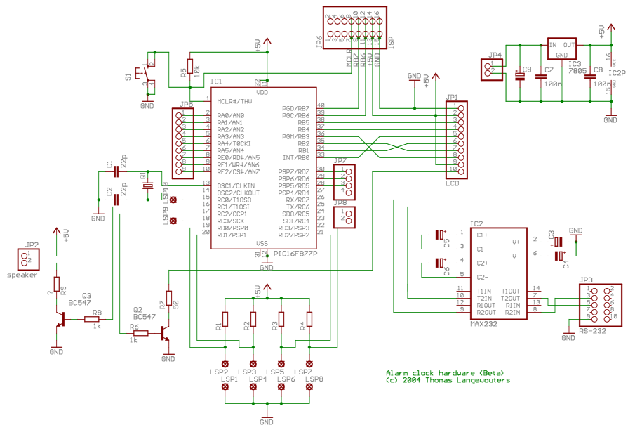
This project outlines a digital clock featuring an alarm function, utilizing a PIC16F877 microcontroller to achieve an accurate 1-second delay with Timer0 through Roman's zero error method. The time is displayed in large font on a 4G—20 character LCD,...
Creating projects that connect to the phone line can be a real chore without some device like this. It generates the 48 volts DC for the on-hook condition, the 100 volts AC for the ring signal, and the 20...
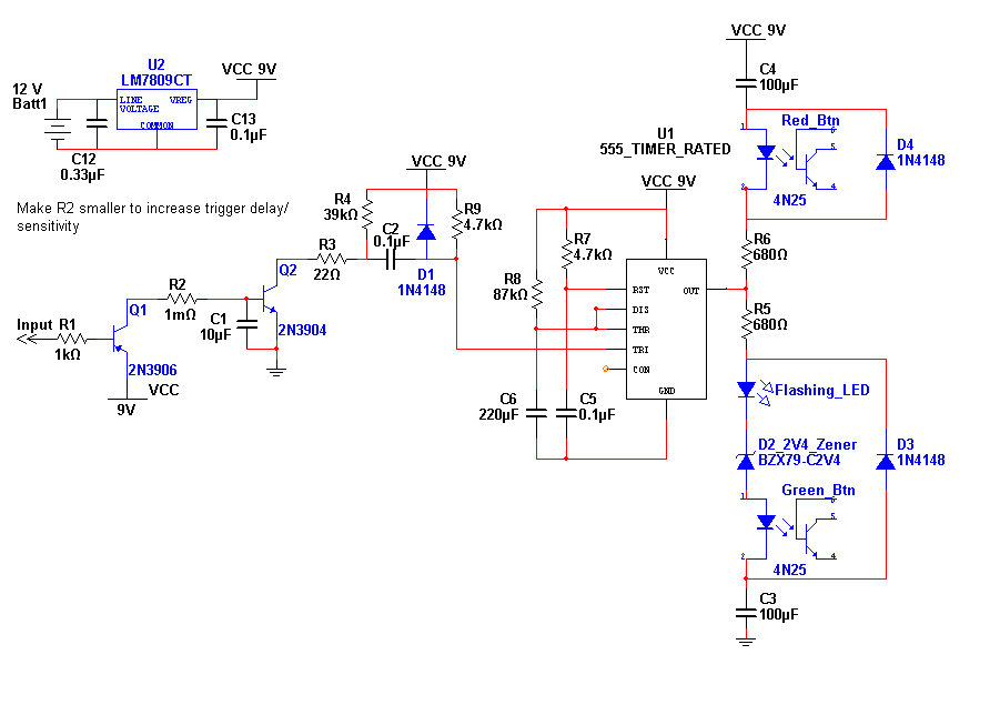
This entry is for the international 555 Contest. The 555 timer chip has been in use for many years and is highly versatile. The concept of this project addresses the need for notification of an event while away from...
Interface the LCD with the 8051 microcontroller AT89S52. However, upon powering up the microcontroller, the LCD displays only black boxes. Multiple codes have been tried, but the output remains the same. The circuit has been simulated in Proteus, where...
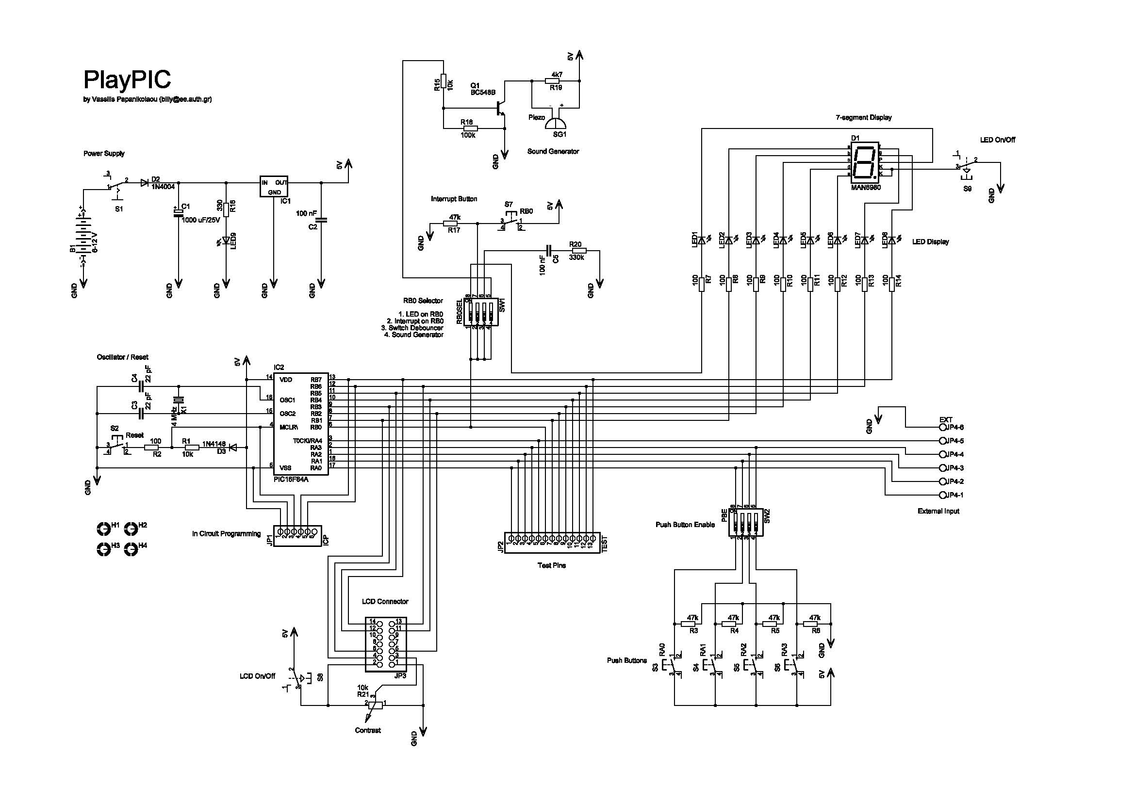
This is a new design of a tutorial board based on the popular PIC16F84A microcontroller. It features eight single LEDs, a 7-segment display, an LCD display, and five push buttons. It is an ideal solution for the beginner to...
The second component is a Signal Distribution Board that transmits voltage, ground, and various signals throughout the system. This board is based on the design found on its dedicated page: Signal Distribution Board. The 7400 pick system is equipped...
Warning: include(partials/cookie-banner.php): Failed to open stream: Permission denied in /var/www/html/nextgr/view-circuit.php on line 713
Warning: include(): Failed opening 'partials/cookie-banner.php' for inclusion (include_path='.:/usr/share/php') in /var/www/html/nextgr/view-circuit.php on line 713