
PIC Freq Counter
The prescaler circuit is designed to divide the input frequency by a predetermined factor, enabling the PIC microcontroller to measure higher frequency signals accurately. The circuit typically consists of a high-speed comparator, a flip-flop, and additional logic components to ensure proper signal conditioning and division.
The input frequency range of 1 MHz to 400 MHz requires careful selection of components that can operate effectively within this bandwidth. High-speed operational amplifiers or comparators should be used to maintain signal integrity, while the flip-flop should be capable of toggling at the desired frequencies without introducing significant propagation delay.
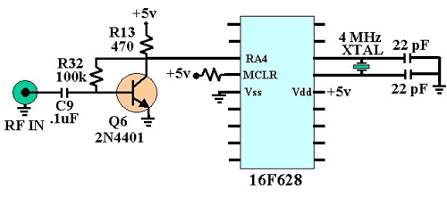
To implement the prescaler, the input signal is first fed into the comparator, which converts the analog signal into a clean digital square wave. This digital output is then connected to the clock input of a flip-flop, which divides the frequency by two. If a higher division ratio is required, additional flip-flops can be cascaded.
The output of the prescaler can be interfaced with the PIC microcontroller's input pins, allowing it to count the pulses and thereby determine the frequency of the original signal. The microcontroller can be programmed to display the frequency on an LCD or transmit the data for further processing.
In summary, this prescaler circuit serves as a crucial component for frequency measurement applications, enabling the PIC microcontroller to handle a wide range of input frequencies while maintaining accuracy and reliability. Proper attention to the selection of components and circuit design will ensure optimal performance across the specified frequency range.A prescaler attached to a PIC to get a simple frequency counter. I would suspect that it would just become a "module" that I include in some other design projects later. Initially I need to get a working sample. Target range would be 1mhz through 400mhz. 🔗 External reference
Related Circuits
This circuit was formed to create a wireless alarm from a normal magnetic contact. By fixing the magnet to the leaf of a door, or swing of a drawer, it is easy to reveal the opening. To transmit the...
National Instruments Multisim now features microcontroller unit co-simulation capabilities, enabling the inclusion of a microcontroller, programmed in assembly or C code, within SPICE-modeled circuits. The MCU functionality in Multisim allows students, educators, and professional users to program MCUs in...
The receiver chip uses a Panasonic 4602 38KHz receiver and that's it for external components. It has the serial input (GP3), two RC hobby servo outputs (GP0/GP1), and three digital outputs (GP2,4,5). Here is the code for the receiver...
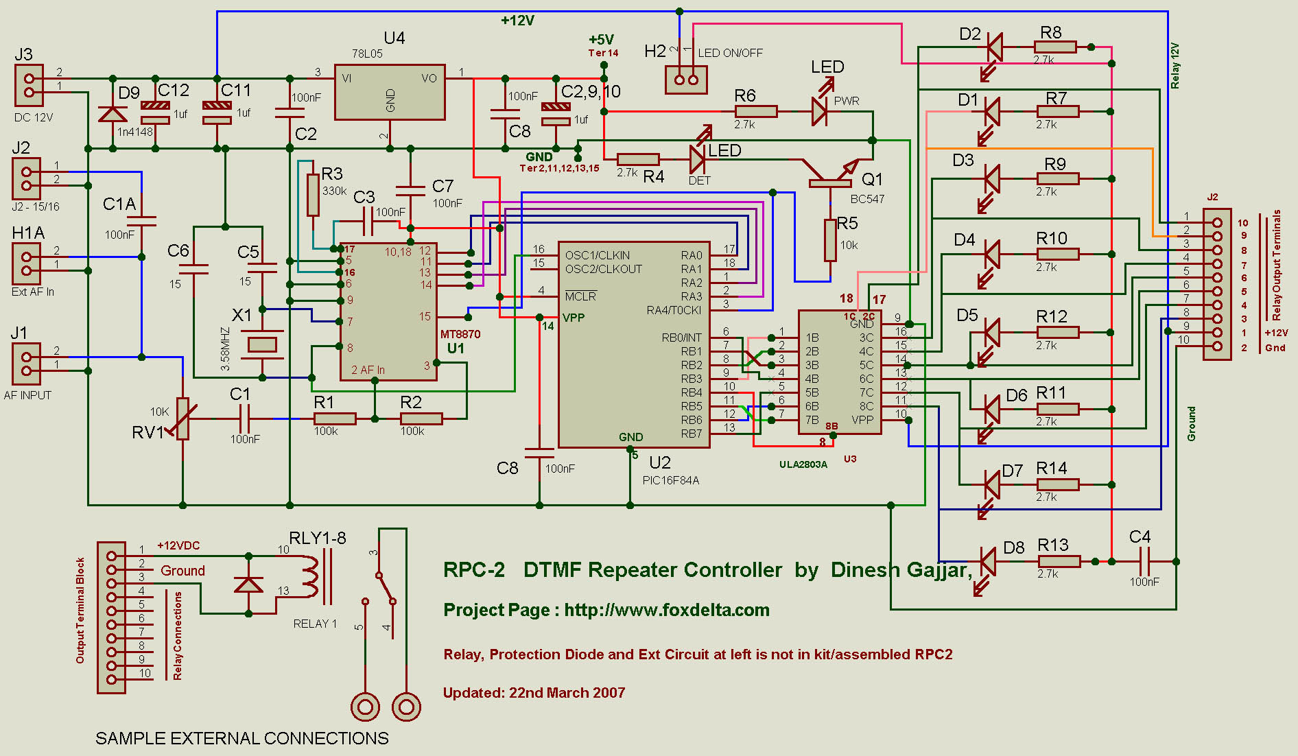
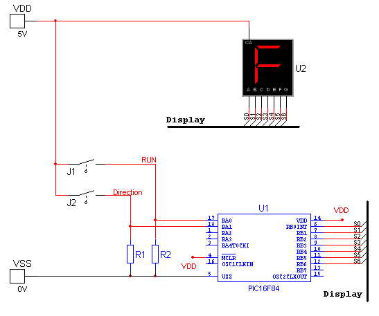
This DTMF controller, based on the PIC16F84A microcontroller, is straightforward and cost-effective to construct. It provides practical experience in utilizing and programming PIC microcontrollers. The controller measures 10 cm x 6 cm and can be housed within a repeater...
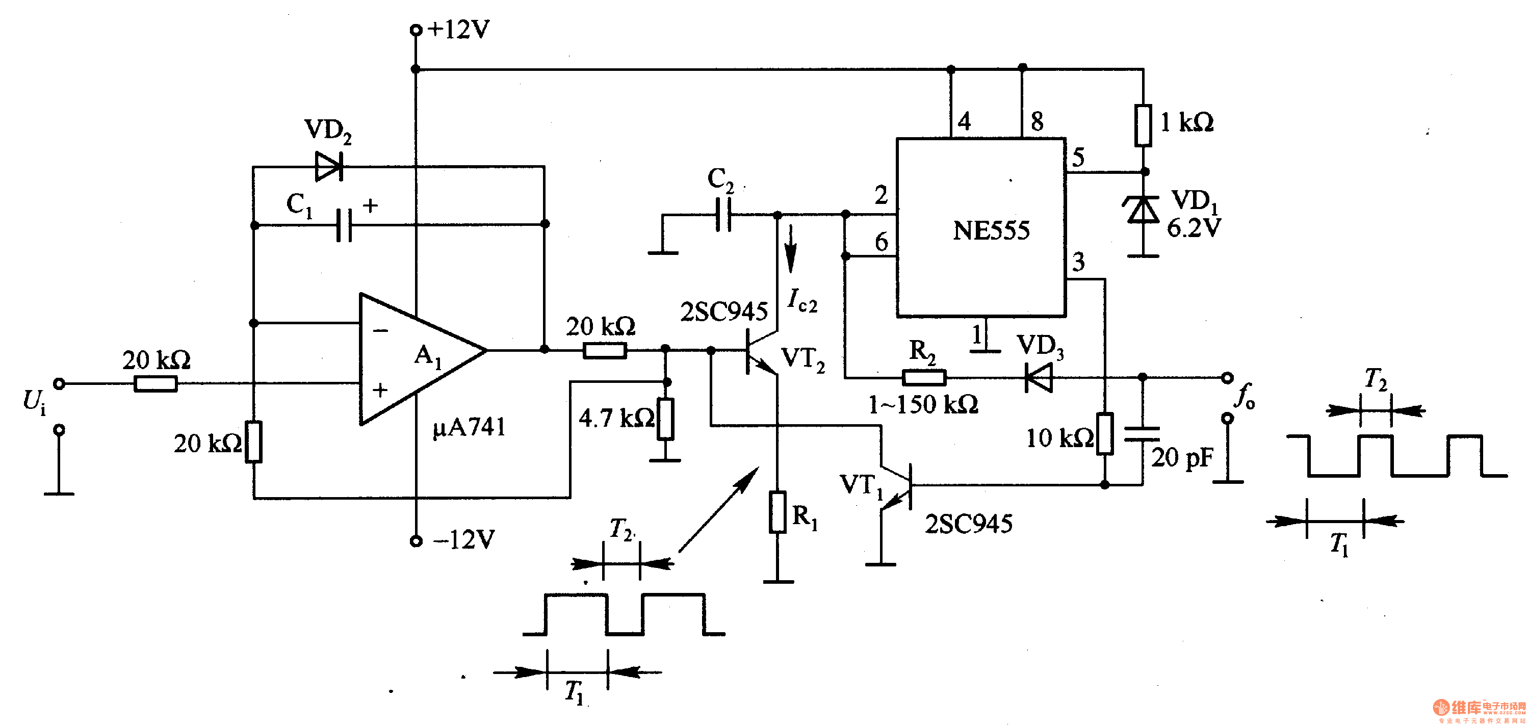
In the circuit, the oscillation frequency of the NE555 is controlled by VT2. When the output at pin 3 is low (during the T1 period), VT1 stops conducting, and VT2 begins to conduct with a current Ic2 flowing through...
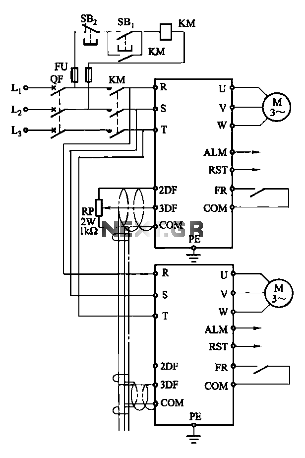
Each motor operates with an independent drive; however, only one frequency is utilized for a specific device. This setup employs a single RP potentiometer to control multiple motors in parallel. In this configuration, the circuit design allows for multiple motors to...