
IR Encoder/Decoder with PIC12C508
The described circuit features a Panasonic 4602 38KHz infrared receiver integrated into a compact electronic system designed for a remote-controlled vehicle, referred to as the "Rhino." The receiver is connected to a microcontroller that interfaces with various outputs, including two RC servo outputs (GP0 and GP1) and three digital outputs (GP2, GP4, and GP5). The GP3 pin serves as a serial input for receiving commands.
The digital outputs are configured as momentary contact type outputs, which means they generate a short pulse when activated, suitable for triggering external devices such as sound boards. The design omits the use of GP2 in the current configuration, streamlining the circuit for its intended purpose.
Powering the receiver is a 4-cell NiCd battery pack rated at 115mAh, which is compact enough to fit within the vehicle's design constraints. The transmitter circuit includes five pull-up resistors and an infrared LED, which is driven by a 330-ohm resistor to limit current. A 78L05 voltage regulator is employed to provide a stable 5V output from a 9V battery, ensuring compatibility with the microcontroller and other components. The system can also operate on 3 alkaline cells or a voltage range of 4.5V to 5.5V.
The transmitter reads the status of five momentary contact buttons, prioritizing their input based on bit values to simplify the command transmission process. Commands for directional movement (forward, reverse, left, right) are sent alongside additional signals such as 'go' and 'motor noise.' A built-in delay mechanism allows for the transmission of a 'stop' command if a button is briefly pressed and released, enhancing control during operation.
The overall design includes two LEGO micro motors for propulsion, which are connected to LEGO medium pulleys through rubber bands and mounted using LEGO axles. The motors are controlled via the internal circuitry of old hobby servos, creating a bi-directional motor driver setup that requires minimal I/O lines. The compact dimensions of the receiver board (1 inch by 1.5 inches) and battery pack (1 inch by 2 inches by 0.5 inches) facilitate integration into the vehicle, which employs a "tank" steering mechanism for maneuverability. The incorporation of a pivot ball near the rear reduces friction, contributing to smoother movement.
Schematic diagrams for both the transmitter and receiver sections, along with the associated battery and motor driver configurations, are available to provide a visual representation of the circuit layout and component connections. The receiver chip uses a Panasonic 4602 38KHz receiver and that's it for external components. It has the serial input (GP3) , two RC hobby servo outputs (GP0/GP1) and three digital outputs (GP2,4,5). Here is the code for the receiver chip. It is a bit of a specialty in that the digital outputs are actually "momentary contact" type outputs because I only needed a pulse to go out to trigger a cheap sound board I got from a $6 toy!
I don't even use the GP2 output in this design. The receiver uses 4 NiCd 115MAH cells, the largest set I could fit into the Rhino! The transmitter chip uses 5 pullup resistors and an IR LED powered through a 330 resistor - quite a bit of power I think. To keep things simple, I used a 78L05 to power the PIC so I could use a 9V battery and keep the whole project box size small.
It will run fine on 3 alkaline cells, or, from 4.5 to 5.5V. The transmitter reads the status of the 5 momentary contact buttons and decides what messages to send to the receiver. Here, I give priority by bit value, just so there needs to be no encoding and it keeps the code simple.
Also, when a direction command is given (forward, reverse, left, right) I also give the 'go' command and the 'motor noise' commands. If a button is pressed and immediately released, the transmitter waits a couple seconds and sends the 'stop' command.
This allows you to hold a button down, issue a series of commands continuously but still stop nicely. The transmitter issues a constant stream of 'stop' commands when no button is pressed. This is a nice troubleshooting method as well as insuring that the unit doesn't just take off! Here is the code for the IR transmitter. Building the Rhino was a challenge. It is about 5 inches long and about 3.5 inches wide and about 2 inches tall. Into that I needed to put a battery pack, two motors, two motor drivers, the IR receiver board and actual drive wheels and wiring with a sound board and speaker.
Wow. I used two LEGO micro motors for the drive motors, they were connected to two LEGO medium pulleys via rubber bands and held in place using two-stud LEGO axels through a two stud Technic rail - If you know LEGO, you know what I mean by that. I drove the motors by connecting them to the "guts" of two old hobby servos. This gave me two small bi-directional motor drivers that I only needed a single I/O line to control. The receiver board was about 1 inch by 1.5 inches and had the IR receiver sticking out the top of the model.
The 4 cell 115MAH NiCd pack was about 1 inch x 2 inch by 0.5 inch, very small! I used "tank" steering and mounted a pivot ball near the back of the tank to lower friction. Below are the schematics for the transmitter and receiver sections including the battery and motor/driver setups as I installed them. I only needed to make a couple of smalll internal mods to get all of the stuff to fit. 🔗 External reference
Related Circuits
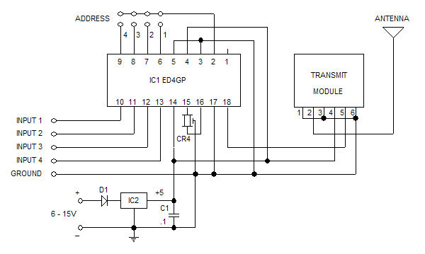
The Glolab ED4GP microprocessor-based Encoder/Decoder is designed for use with wireless modules, infrared remote controls, and other devices that operate with serial input and output data. It can function as either an encoder or a decoder by connecting pin...
We hold the first rights to the presentation of this approach and the best part is: It's FREE! The PIC12C508A is one of the most amazing devices but because it does not come in a low-cost re-programmable form, it...

The MT8870 is a complete DTMF receiver that integrates both the band-split filter and digital decoder functions. The filter section employs switched capacitor techniques for high and low group filters, while the decoder utilizes digital counting methods to detect...
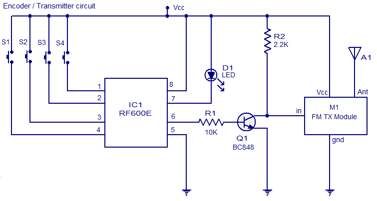
The circuit diagram illustrates an FM remote encoder/decoder utilizing the RF600E and RF600D integrated circuits (ICs). These components are engineered to deliver a high level of security and operate within a voltage range of 2 to 6.6V DC. Applications...
The schematic of the SAVER V3.2 is depicted in Figure 1. A transformerless power supply uses Xc of a 0.22uF capacitor to limit current, providing about 10mA current source. The diodes rectify AC current to DC current, which in...
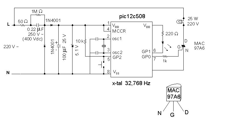
Introduction It is time for the 8-pin microcontroller Microchip PIC12C508, the SAVER V3.2, a new design of a device that controls a night light by turning it on and off. The SAVER V3.2 utilizes the Microchip PIC12C508 microcontroller, which features...