
PIC Frequency Counter with Frequency Lock
The circuit utilizes the PIC microcontroller to manage frequency measurement and locking. The operational amplifier TL082 is employed for signal conditioning, providing both integration and buffering functions. The integration process is crucial for creating a smooth control signal that adjusts the oscillator frequency gradually, preventing abrupt changes that could destabilize the system. The use of a trimmer potentiometer allows for fine adjustments to the scaling of the control signal, ensuring that the oscillator can be precisely tuned to maintain the desired frequency.
The digital outputs RB0 and RB3 serve as control signals to activate the transistors Q2 and Q4, respectively. These transistors act as switches to ground the integrator input or apply a voltage, thus controlling the output of the integrator in response to the frequency difference calculated. The design ensures that only one transistor is activated at a time, preventing potential damage from short circuits.
The frequency locking mechanism is designed to maintain stability within a specified tolerance of +/-20 Hz. The operational amplifier's slow control response is intentional, allowing the VFO to settle without rapid fluctuations. The feedback loop created by the integrator and the buffer ensures that the oscillator remains locked to the target frequency over time, adapting to any drift that may occur due to temperature changes or other environmental factors.
Overall, this circuit design exemplifies a robust method for frequency stabilization in oscillators, utilizing microcontroller logic, analog signal processing, and careful component selection to achieve reliable performance in various applications.This PIC software combines frequency counter and frequency lock functions. By adding couple of transistors and operation amplifier TL082, it is possible to lock the LC oscillator frequency. Frequency reference is formed from the measured frequency itself after the delay defined by parameter 0Dh, when the number of the consecutive samples (defined
by 0Eh) of measured frequency are within the +/-20 Hz. Then the actual value is trigged as frequency reference until the SW detects that the lock conditions are not valid. Frequency is measured every 100 ms. Next the frequency actual is subtracted from the reference and the difference is compared to value zero to calculate the deviation.
If the result is zero, it means that no deviation and also no need to fine-tune the oscillator frequency. If the result is negative it means that the frequency actual is higher than reference. This detects the direction of the needed frequency correction. Next the rough value of the difference is calculated. If within 20 Hz then only short 2. 4 ms pulse is controlled. If bigger then 100 ms pulse is controlled. By means of these few calculations we have information how to fine-tune the frequency of the oscillator to hold the frequency actual equal as frequency reference.
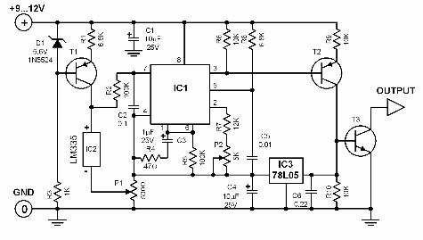
Simple, is it These pulses are controlled to digital outputs RB0 or RB3 according to the sign of the frequency difference. The outputs are never simultaneously on because it means almost short circuit. The controller is made using TL082 operation amplifier. The first amplifier is an integrator by means of the capacitor C8 and R23. A time constant is R23 * C8 = 22 M Ohms * 2. 2 uF = 48 s. So the control is slow and it only fine tunes the oscillator frequency and this is of course the purpose of the controller.
The VFO itself must be stable enough. Second amplifier of TL082 is connected as a buffer. If the PIC SW controls the output RB0 to state TRUE, then led D4 is light and Q2 saturates. It connects integrator input via R23 to GND and the voltage at the output pin 1 changes to positive direction. If the RB3 is controlled to state TRUE, D4 is light and Q3 connects the base of the Q4 to ground. As a result Q4 is saturated and +9 V is connected to the R23. Now output changes to negative direction. If none of RBs are controlled, the integrator acts an analogue memory. It holds the last value at the output. This suites well for the situation where the subtraction result of reference and actual is zero. The used transistor types are not critical. It must be added a capacitance diode connection to the oscillator circuit. See area A in the schematic diagram. This additional connection changes the frequency range of the oscillator. So it must be compensated by tuning the frequency range of VFO, if necessary. Output of the buffer amplifier (pin 7) is connected to the trimmer potentiometer R25. This is used to scale the effect of pulse to the oscillator frequency. If the previous tests and settings have been successfully performed, it is a time to do connections between the frequency counter and frequency lock printed boards as well as connections to the oscillator circuit.
Activate the Freq_Lock function by par. 0Bh. Reconnect the voltages to the boards and start to observe the LEDs D3 and D4. When the frequency reference has been sampled and set, the character L is displayed in the LCD. Observe the LEDs. Only short pulses should be seen seldom if there is a need to fine-tune the oscillator frequency. Long pulse can only been seen if the VFO drifts over 20 Hz within the 100 ms. A long pulse can be seen as a bright light (D3, D4) and short pulse as a dimmed one. The VFO that I have used in my transceiver, with the warm oscillator only few pulses can be seen during the 10-second period. At the beginning with cold VFO long pulses with short ones can also be seen. The effect of the control is too big, if correction to one directio 🔗 External reference
Related Circuits
The locker alarm circuit, also known as the cashbox watcher, is designed to safeguard a cashbox or locker from unauthorized access. This reliable design features a foolproof, remotely operated alarm and electromagnetic relay driver that receives its control signal...
In certain temperature measurement applications, converting the measured value into a frequency rather than a voltage offers distinct advantages. A temperature-to-frequency converter can be directly interfaced with a frequency counter or connected to a computer without necessitating an A/D...
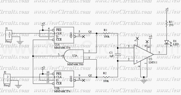
This circuit uses a 74HCT74, 74HCT00, and a LM311 to form a frequency comparator. The two pulse trains are fed to two D-type flip-flops (triggered by the leading edges). The flip-flops' outputs are compared in a NAND gate. If...
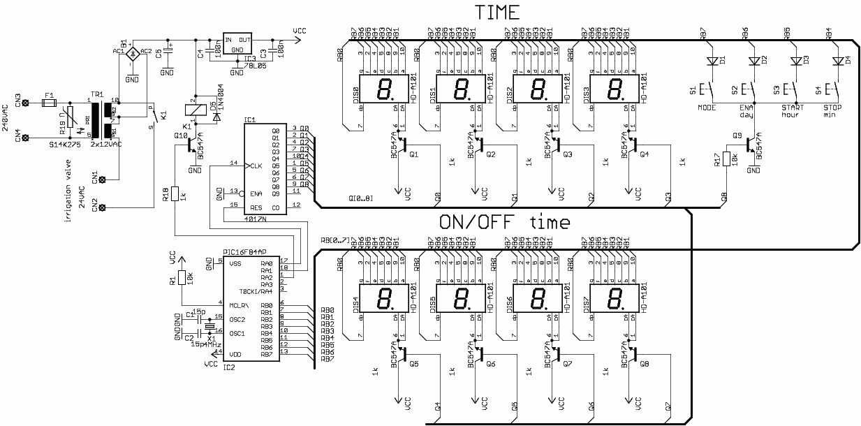
This is a simple one-valve irrigation controller made for our greenhouse. The code contains a software real-time clock (RTC) and a multiplexed 8-digit LED display and keyboard you can use in other projects. The operating software is simple, it...
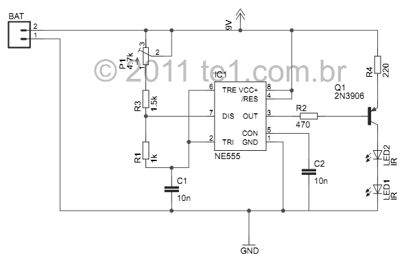
This small device is designed to jam remote controls by directing it at the TV. The circuit utilizes a 555 timer configured as an astable multivibrator, generating a frequency of approximately 38 kHz, which corresponds to the frequency at...
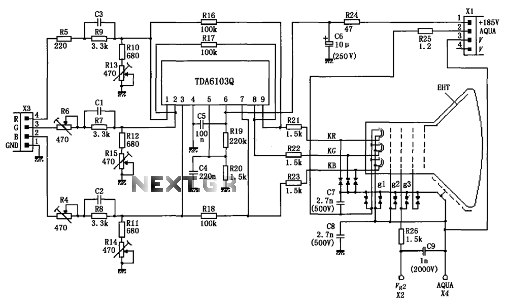
The circuit depicted in the figure integrates the TDA6103Q with a color picture tube, illustrating its practical application. The red, green, and blue (R, G, B) input signals are received from the input socket X3 and processed through a...