
2 Input Pulses Frequency Comparator
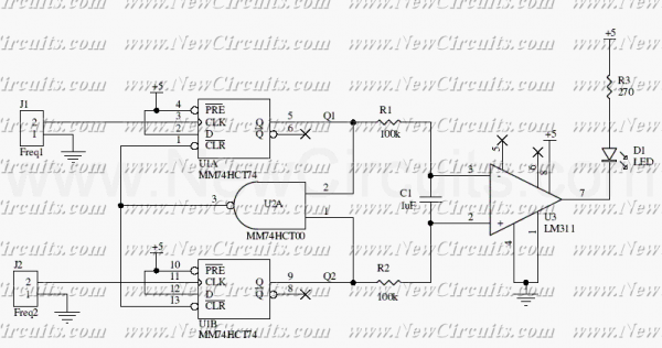
The described circuit implements a frequency comparator using a combination of digital and analog components to evaluate and compare the frequencies of two input signals. The core of the system is formed by two D-type flip-flops (74HCT74), which are configured to capture the leading edges of the incoming pulse trains, F1 and F2. The outputs of these flip-flops, denoted as Q1 and Q2, are then fed into a NAND gate (74HCT00). The NAND gate serves as a logic element that resets the flip-flops when its output is low, indicating that the frequencies of the two signals are equal or that F2 has a higher frequency than F1.
In the operation of the circuit, if F1 has a higher frequency than F2, Q1 will produce a continuous pulse train while Q2 will exhibit a needle-like output. This behavior indicates that the energy content of Q1 is greater than that of Q2, which can be utilized for further processing or signaling.
To ensure that the signals are clean and free from high-frequency noise, Q1 and Q2 are passed through a low-pass filter, which is composed of resistors R1, R2 and capacitor C1. This filtering stage smooths the pulse trains, allowing for a more accurate comparison of their average levels.
The filtered signals are subsequently fed into an analog comparator circuit (LM311), which compares the amplitudes of Q1 and Q2. The output of the LM311 can drive an LED, providing a visual indication of the comparison result. Additionally, this output can be utilized as a digital signal, allowing for integration with other digital logic circuits or microcontrollers for further processing or control applications.
This frequency comparator circuit is valuable in various applications such as frequency measurement, signal integrity testing, and in systems where frequency monitoring is critical for performance optimization.This circuit uses a 74HCT74, 74HCT00, and a LM311 to form a frequency comparator. The two pulse trains are fed to two D-type flip-flops (triggered by the leading edges). The flip-flops' outputs are compared in a NAND gate. If the output of the NAND gate becomes "0", the flip-flops are reset. If the frequency of F1 is higher than the frequency of F2, the signal "Q2" consists of needles and "Q1" is a pulse train. Therefore, the energy content of Q1 is higher than that of Q2. Q1 and Q2 come via a low-pass filter (consisting of R1, R2 and C1) and are compared by an analog comparator circuit (IC3). The comparator drives an LED and can act as a digital output. For the 🔗 External reference
Related Circuits
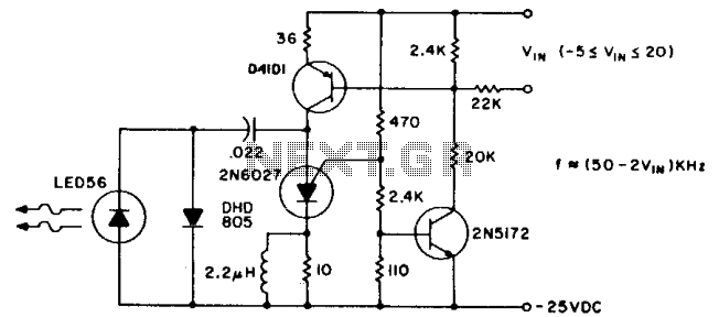
The pulse repetition rate is largely unaffected by temperature and power supply voltage, and it varies linearly with V1N, the modulating voltage. Effective information transfer was achieved at distances of 12 feet (~4m) in free air. A greater range...
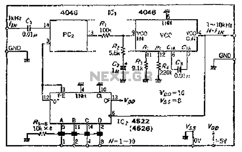
The CMOS IC 4046 Phase-Locked Loop (PLL) operates with a maximum frequency of 1 MHz. It is connected to a programmable divider, allowing it to process input frequencies. As the frequency increases by a factor of t, the circuit's...
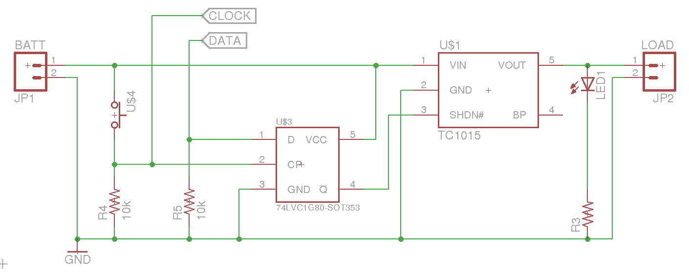
A soft power switch for a microcontroller is designed such that a momentary switch can activate the circuit, including the microcontroller. When the switch is pressed a second time, the microcontroller is capable of shutting itself down after executing...
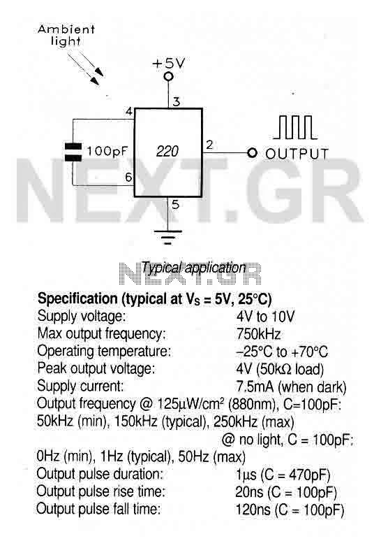
A large area photodiode and current-to-frequency converter integrated into a clear plastic 8-pin DIL package. The output generates a pulse train whose frequency is directly proportional to the light intensity. It is CMOS compatible (a 3.3kΩ pulldown resistor is...
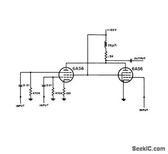
Distance markers and if signals are inserted at separate grids on one tube, while radar video from input 3 is impressed on the control grid of another pentode. In this circuit design, the integration of distance markers and intermediate...
The preamplifier is based on the LM733 or NE592, featuring a bandwidth of 100 MHz. The FET inputs offer an input impedance of approximately 1 MΩ. Signal conditioning is achieved through the use of Q4, Q5, and IC2. The...