
Pic microcontroller project

The following hex file are use Microchip Math Library (assembler code) for this simple multi channel digital voltmeter device (using 16 bit for calculation). The maximum hex value for the ADC channel is FFF equal to decimel number 4095. This will display on the LCD as 5. 11 volt. Download hex file for Pic16F84 here: F84dec. zip. Download hex file for Pic16F628 here: 628dec. zip. If using PORTA pins as interfacing I/O, you need to define/set the I/O fuction for PIC16f628. Generally, the initial PORTA setting as following for I/O fuction: clrf PORTA movlw 0x07 ;turn comparators off and movwf CMCON ;enable pins for I/O functions Note: Ensure the above setting done at Bank 0.
The above setting especially important if you want to migrate the source code from Pic16f8X series to Pic16f62X series. Always refer to data memory MAP (on Pic datasheet) to ensure that the general purpose register used not out of range when migrate one type of MCU to another type of MCU.
As example, general purpose register for Pic16f84 was 0x00c to 0x04f (at bank 0). For Pic16f628 was 0x020 to 0x07f (at bank 0), 0x0a0 to 0x0ef (at bank 1) and 0x120 to 0x14f (at bank 2). It is better to define the address follow sequence. If out of range, you can re-define it easly. When Using bit 4 (RB4) of PORT B of Pic16F62X series as a output pin, ensure that the MCU not programmed at low voltage program mode (see Microchip datsheet) if not it will set as Schmitt Trigger input and independence of TRISB regeister I/O direction setting.
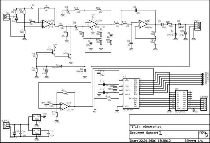
The opto-isolator are important which prevent destroy of MCU by the feeback voltage from power transistor. Two adjust-able voltage regulator used to adjust the running voltage and stopping/holding voltage of the stepper motor.
The running voltage on by the step pulse input which also signal to rotate the motor. The simple source code using interrupt method to change the step sequence (one wave) download here: F628_stepper for Pic16F628. Simple mathematics algorithm able to drive more complicate step sequence (such as half step) even for half_step 5phase stepper.
Another stepper motor circuit for X-Y table project click here: X-Y table project The numerical LED display module was widely used in display application. The most common numerical LED display module consists of either 8 segmented or 16 segmented LED units.
However, this type of display module only limited to display numerical character (0 to 9) and a few type of alphabet character. Most of alphabet word message displayed using alphanumerical LED modules with dot matrix arrangement.
The 24 segments LED display module designed in such a way that enable it to display alphabet (A to Z) and numerical (0 to 9) character. Th 🔗 External reference
Related Circuits
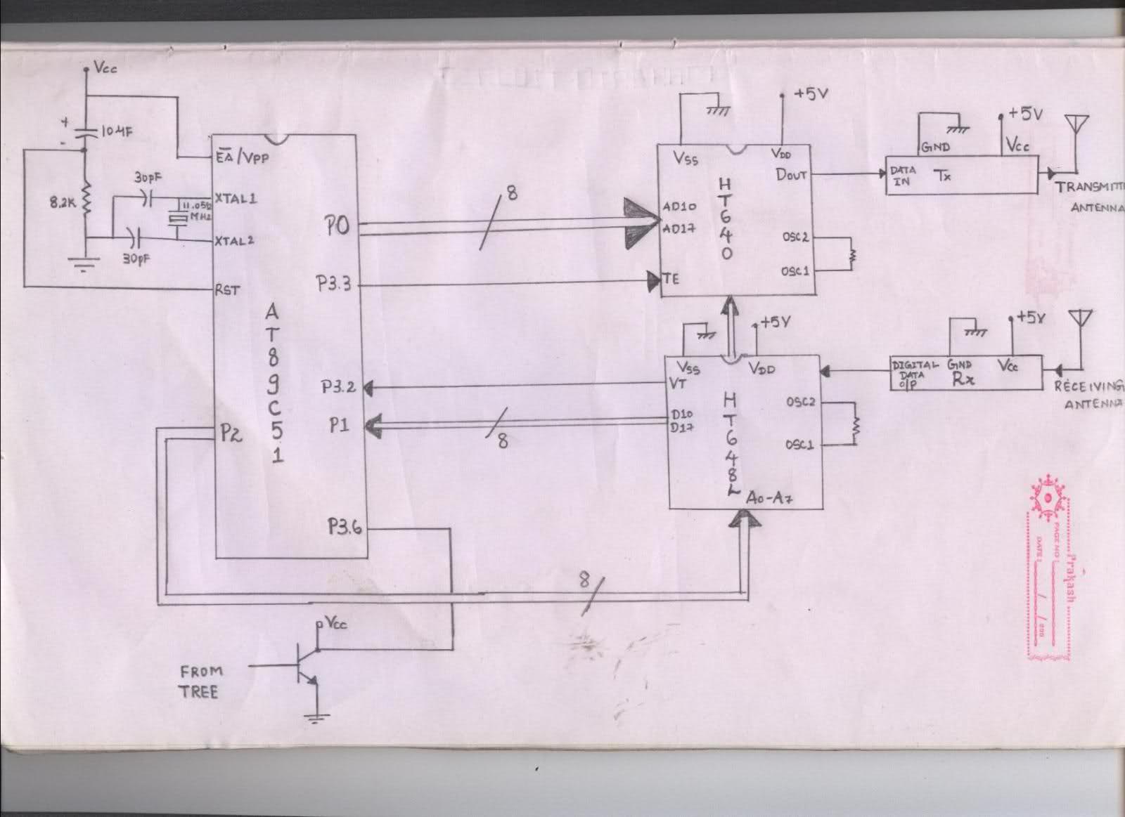
The issue arises when connecting the 8051 microcontroller to the HT640 encoder; the data sent is not received at the receiver. However, when the connections to the 8051 are removed, the transmission functions perfectly. This indicates that manual RF...
The drawings and photos below are for an operating incline railway that was built by the London Model Railroad Group for its O scale model railway club located at London, Ontario, Canada. This is a single car model loosely...
This is an early picture of my discolight effect. Because of the AGC circuit, there's no need for potentiometers for sensitivity adjustment. I replaced them with trimmers. Now the microphone is on the control electronics because there's no need...

A simple lab power supply electronic project can be designed using this circuit diagram, which is based on the LM2576 monolithic integrated regulator that provides all the active functions for a step-down (buck) switching regulator. As seen in the...
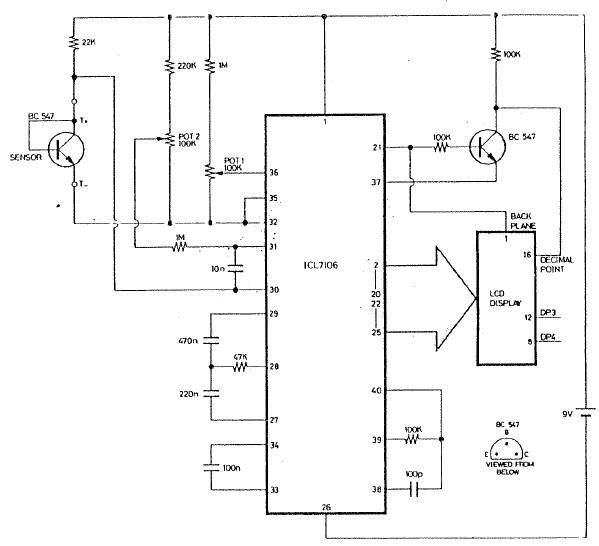
The ICL7106 integrated circuit contains all the active circuitry for a 3 1/2 digit panel meter (DPM) in a single chip. It was designed to interface directly with a liquid crystal display (LCD). The potential difference across a silicon...
Microcontrollers and Microprocessors - The 8051 Projects Page! Discover comprehensive information on 8051 projects here. Everything you wanted to know about 8051 projects is available. The 8051 microcontroller, developed by Intel in the 1980s, is a widely used microcontroller in...