
PIC Programmer schematic RS232
The universal PIC programmer described allows for programming a variety of PIC microcontrollers, including the PIC12C5XX, 12C67X, 16C55X, and many others, through in-circuit serial programming (ICSP). The JDM programmer is highlighted for its simplicity and effectiveness, requiring only a few components such as a cable clamp IC, a 100-ohm resistor, and a 5V power supply. The programmer can operate directly from a serial COM port, which provides the necessary voltages for programming, including Vpp.
The IC-Prog software is crucial for operation, enabling users to read, write, and erase data from the microcontrollers. Configuration settings are necessary for proper functionality, particularly under Windows XP, where compatibility adjustments may be needed. The inclusion of a blocking capacitor on the RB6 and RB7 lines is important for stability, especially when using longer wiring.
The circuit design of the programmer incorporates various components, including resistors, capacitors, and diodes, to manage voltage levels and protect against over-voltage conditions. The use of transistors allows for switching and level conversion, ensuring that signals are appropriately handled.
Overall, the JDM programmer serves as a versatile tool for programming PIC microcontrollers, with a focus on simplicity and accessibility for hobbyists and engineers alike. The detailed schematic and component specifications provide a comprehensive guide for those looking to build or modify their own PIC programming solutions.In the article you will find a description of the universal PIC programmer, which suggested the involvement of Jens Madsen Dyekjar [ http://www.jdm.homepage.dk/newpic.htm ]. Program allows districts PIC12C5XX, 12C67X, 16C55X, 16C61, 16C62X, 16C71, 16C71X, 16C8X, 16F8X, serial EEPROM 24Cxx.
It allows to program the microcontroller directly involved (ICSP) and other adapter series programmable components, such as ISO cards. When I needed some time to program the PIC microcontroller, I decided to build a programmer. This solution seemed more operative than I repeatedly asked someone on the programming of their friends.
PIC programmers on the Internet can find a large number, but these are a few options involved. Ease programmers, especially excel to be attached to a serial COM port. In search of my choice fell on JDM programmer. The simplest PIC programmer is very simple. As shown in Figure 1 , sufficient to build the cable clamp IC, a 100 ohm resistor and voltage source of approximately 5 V [ http://www.jdm.homepage.dk/easypic.htm ]. The programmer is not too shabby programmed circuit. To reduce the voltage applied intercepting internal diode and power supply. According to remarks in the discussions is also the function of the rather unreliable. A slightly more complex programmer according to Figure 2 no longer needs an external power source [ ftp://ftp.ai.uga.edu/pub/microcontrollers/pic/ludipipo.zip ].
Common infirmity of those two is the lack of involvement of voltage Vpp, which is obtained directly from the serial COM port. The circuits are powered port voltage ± 12 V from a source computer, the laptop just double voltage of 5 V.
Control Program IC-Prog is freely available on the Internet [ http://www.ic-prog.com ]. Allows you to program to retrieve data from files in several formats, read, erase and program the microcontroller to write, edit and set the data type of the oscillator and the "fuse". First you must select the type of programmer (JDM, the very first item). In Windows XP, the program will not work without additional configuration. In p?zkumníku icprog.exe locate the file. Use the right mouse button and select Properties from the menu and Compatibility "Run in compatibility mode with Windows 98/Me or 2000.
Ok. By the same directory as the program icprog.exe icprog.sys upload the file. After starting icprog.exe select Settings, Option, Misc and check the option "Enable NT/2000/XP Driver". Icprog.sys file as you download the program from a website [4] under the name NT/2000 driver. I programmer works under Windows XP without a driver and setting kompatibity. When I run the control program in the Settings menu, choose hardware instead of "Direct I / O" "Windows API.
I would like to state in advance that my experience with the PIC are slim. I just needed to program the PIC, so I built the JDM programmer, and according to PIC (16F84) successfully programmed. The following information was obtained from correspondence with people whom the programmer did not work.
I would also like to thank Andrew Spilka, from the e-mail based on the following text, which I drew attention to a problem with blocking capacitor. Sometimes I receive an e-mail to someone that the programmer does not work. There may be several. The most common is probably a mistake in wiring cable. The recovery is advantageous to use IC-Prog, which has a menu item HardwareCheck where the individual can parget and crashing pins and measure the output voltage.
You could well revive the programmer. If you use a variant of the connector on the motherboard, you must use the connector sockets (female) connector with pins (male) pin is reversed and the programmer does not work. Another problem is probably just some effect. Then you need to block outgoing RB6/CLOCK RB7/DATA against VSS capacitor with a capacity of at least 1 nF.
If used long enough cable wire mezizemními, probably will not be needed. If you connect a capacitor directly, certainly can not go wrong. Blocking capacitor should be closest to the CPU as in the case of on-board ICSP. On the diagram, I added a capacitor on the printed circuit board solder the ceramic capacitor to the terminals of the socket connections. The control program of the IC-Prog can use the "Direct I / O with 2 ms delay, then programs really quickly.
19th 1st 2009: The Microchip 16F627, 16F628, 16F628, 16F648A, 16F870, 16F871, 16F872, 16F873, 16F874, 16F876, 16F877, 16F873A, 16F874A, 16F876A, 16F877, 18F242, 18F248, 18F252, 18F258, 18F442, 18F448, 18F452, 18F458, 18F1320, 18F2330, 18F4320, 18F6620, 18F6720, 18F8620, 18F8720 is the PGM pin should be connected to GND! Eg. 16F62x for circuits within the housing with 18 pins must be linked to pin 10 (RB4 indicated in the diagram) with pin 5 (Vss in the diagram), ie, disconnect it and connect from Vdd to Vss.
JDM programmer for modification for PIC16F628A and Other 18-pin low-voltage PIC programed see Picture 8, 9 and 10th Really works - tested. Microchip PIC programming allows for low voltage (low voltage programming) can be programmed in the JDM programmer, just need to connect the PGM pin to GND (VSS).
Editing programmer is evident from the pictures. First you need to join 2 p?ekrábnout around 10 pin IC socket, then solder the resistor and jumper. Then you can PIC16F628A (and probably other PIC 18pinovém housing) program. It really works - tested. In several attempts, I reprogrammed PIC16F628A programmer and suddenly stopped working. On the advice of Mr. Spilka I added a 1 nF capacitor C1, by mistake (it was enough after midnight) on pin RB7 RB6 place. The programmer then began to work again. What was my surprise this morning when I found out I got it otherwise. I shifted the C1 RB6 and programmer was dead again. I returned it to the RB7 started working again, as with the PIC16F628A, and with the PIC16F84A. Can anyone explain?? Figures 8 and 9 are already fixed. I'm learning to program and PICy p?eprogramovávám is still around. The fact is that the programmer is behaving differently, and no change of 1 2nd did not work for long, after two days the programmer did not work again. I get the impression that this is the Windows API that sends data to the port as he pleases, he still is not a standard port usage.
There I worked to block RB7 kond 1n 4n7 and RB6 of cap to ground. Then the programmer has worked for me a few days anyway. Treatment is again entered in figure 8 and 9, the photo has not changed. R1 10 kOhm R2 1.5 kohm editing for modification 10 kOhm SMD 1206 C1 (edit) 1 nF ceramic (1206) C2 100 uF/16 V submini. C3 22 uF/16 V submini. C4 (edit) 4.7 nF ceramic (1206) D2 Zener diode 5.1 V D6 Zener diode 8.2 V D3, D4, D5, D7 1N4148 Q1, Q2 BC547B mount IC DIL18 CANNON9F plug into the board with a pl.
join connector or cable + cable PCB bcs50 With version 1.06B ICProg I programmed the PIC12F509 (and perhaps PIC12F508). Because the PIC programmer is not on the menu, I chose PIC12C509A. Program it was, well read but not deleted. To clear the need to set another type, I proved to delete the 16F628. What effect has this wild OSCCAL programming, I do not know. The signal port may therefore have a maximum voltage of ± 11.5, respectively. ± 9.5 V. This is much less than the required 13 V. This problem is elegantly solved in the JDM programmer. Programmed IO, there is also powered directly from the serial port, but its positive supply voltage Vdd is connected with PC.
Supply voltage VDC is now -5 V and the signals are obtained with the port. Programming voltage Vpp is now referenced to ground (GND), but the supply voltage VDC. For proper function of the programmer is now just a port output voltage ± 8 V. Involvement of the JDM programmer is Figure 3 , the numbering of components is consistent with genuine involvement. The programmer is slightly more complicated, because the RTS is used as a source of clocked pulses programmed IO and also as a source of supply voltage of -5 V.
The voltage of the conductor is limited and stabilized diode D2 to D4. Capacitor C3 serves as a source of voltage pulse at the time of the RTS pin. Programming voltage diode D6 is limited to about 8 in (ie 13 V against DC). Some variants of the programmer using a zener diode D 6 with a voltage of 6.2 V in series with the LED, which lights up when programming. As the source voltage is used as the TxD signal. Transistor Q1 operates as a switch, the transistor Q2 as a bi-directional converter voltage levels. The original PCB is designed to CANNON with 25 pins. Because the new computer is only a nine-pin connector, I suggested to the board connector. The board programmer can be plugged directly into the connector port (not practical) or use an extension cable.
Even this solution is not happy, because the extension cord is stiff. Finally, I plug the board Desoldered and PC connection cable for use thin at one end is soldered directly to the board programmer, on the second connector fitted. Cable I got from an old mouse. Mouse must be really old, all the newer four-conductor with a supply. Cable must be checked, the mouse might not work for p?elámané cable. For occasional programming to satisfy a common sleeve, the sleeve with a zero insertion force would be more expensive than a few programmers.
In my experience, often stands an ordinary cap more than IO insertion precision sleeve. To program the IO is important only five wires: power Vdd and Vss, the programming voltage Vpp applied to the MCLR pin, clock signal, which is applied to pin RB6 and data signal is applied to pin RB7. These signals are connected to the ICSP connector and can be programmed directly in the circuit diagram (In Circuit Serial Programmining) or other types of programming adapter series of programmable circuits.
The signals of the microcontroller are other outlets ignored. This allowed to engage IC socket so that it was possible to insert the CPU with eight pins and serial EEPROM. 🔗 External reference
Related Circuits
This chapter contains circuit diagrams for several power supplies designed for pulsed solid-state lasers. These include units suitable for driving the widely used Hughes ruby and YAG rangefinder laser assemblies, one utilizing the flash from a disposable pocket camera,...
A mute switch for the Etherwave that adds a "mute status" light, which also functions as a power-on indicator. The schematic is provided. It is recommended to explore the additional resources available on Art's website. The mute switch circuit for...
This circuit is designed for children's entertainment and can be installed on bicycles, battery-powered cars, motorcycles, as well as models and various games and toys. When switch SW1 is positioned as indicated in the circuit diagram, it generates the...
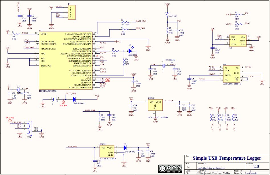
The source code features a FAT12 filesystem that can be utilized to create custom flash drives for various projects. This source code is based on the Microchip Applications libraries for the Device Mass Storage SD Card data logger using...
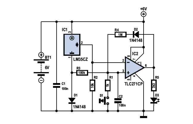
To determine whether it is freezing, one needs to measure the temperature accurately. This requires a reliable temperature sensor. The LM35CZ sensor, which operates within a range of -40 to 110 °C, is suitable for this purpose. It is...
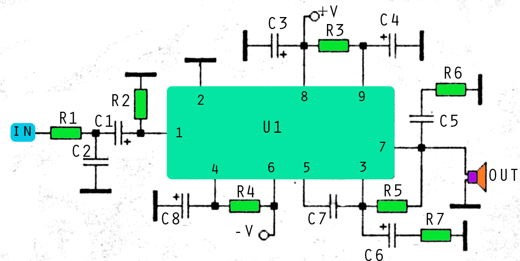
This amplifier circuit utilizes three voltage levels: positive, negative, and ground, with a maximum voltage of approximately 55V DC. The circuit can accommodate several integrated circuits (ICs), including STK 030, 058, 075, 077, 078, 080, 082, 083, 084, and...