
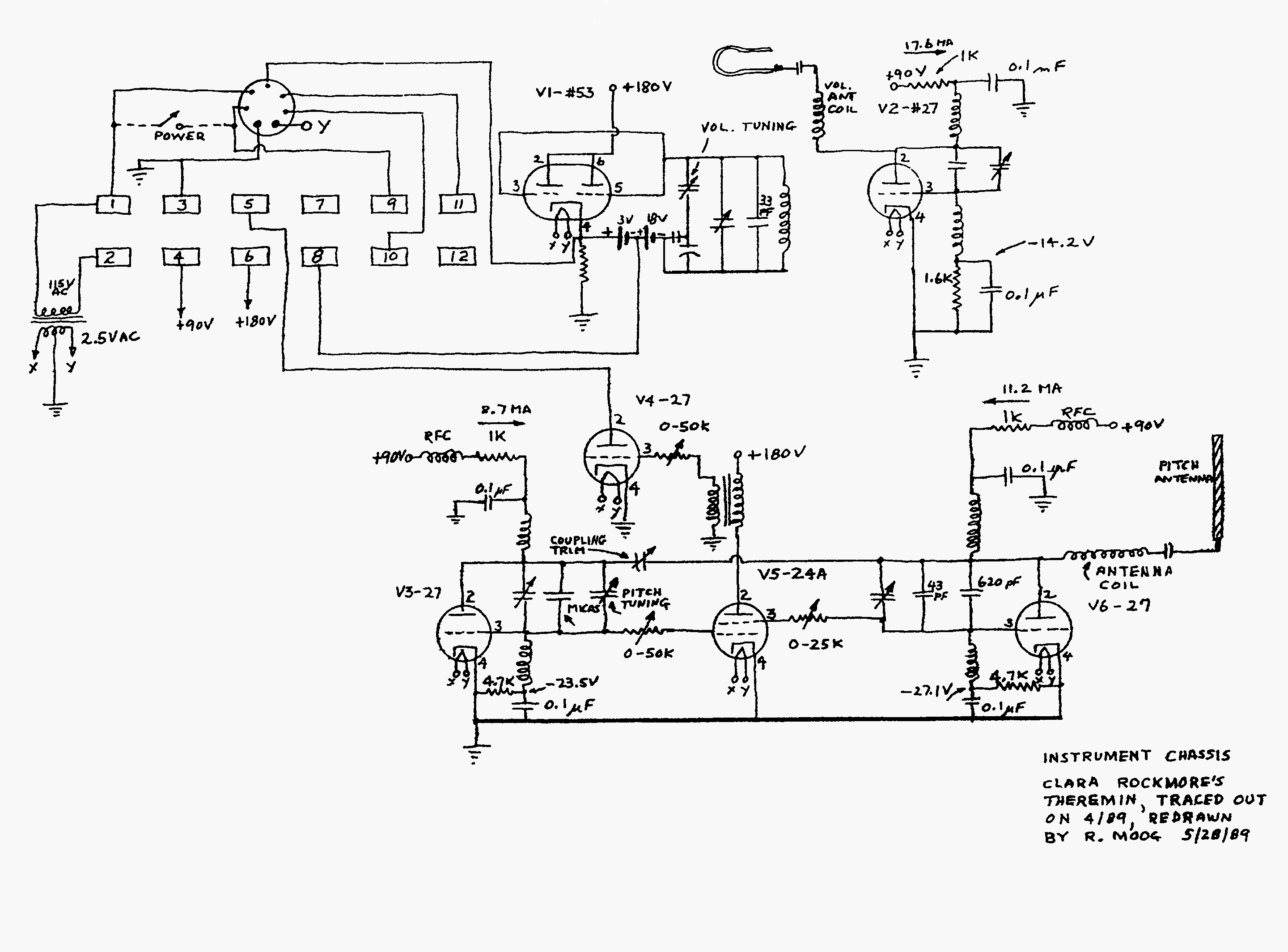
Theremin Schematics
The mute switch circuit for the Etherwave is designed to enhance user experience by incorporating a visual indication of the mute status and power state. The circuit typically includes a toggle switch that allows the user to mute or unmute the output signal. When the switch is in the mute position, the circuit activates an LED indicator, which illuminates to signify that the audio output is silenced. This LED also serves as a power-on indicator, providing a dual function that keeps the user informed about the operational status of the device.
The schematic may include a resistor in series with the LED to limit the current and prevent damage to the LED. A suitable value for this resistor can be calculated based on the forward voltage of the LED and the supply voltage of the circuit. The mute switch itself may be a single-pole double-throw (SPDT) switch, allowing for easy toggling between mute and unmute states.
In addition, the circuit could be designed to integrate seamlessly with the existing Etherwave circuitry, ensuring that the mute functionality does not interfere with the overall performance of the device. Proper layout considerations should be taken into account to minimize noise and ensure reliable operation.
Overall, this mute switch circuit not only enhances the functionality of the Etherwave but also contributes to a more user-friendly interface by providing clear visual feedback on the device's status.A mute-switch for the Etherwave that adds a "mute status" light which doubles as a power-on light. Here`s the schematic. Don`t forget to browse the rest of Art`s great site! 🔗 External reference
Related Circuits
This simple circuit combines two or more audio channels into a single channel (for example, mixing stereo into mono). The circuit is capable of mixing an arbitrary number of channels while consuming minimal power. Although the schematic illustrates two...
Because it uses few parts, a printed circuit board is not necessary; components can simply be soldered to one another. However, a box is desirable for operating convenience. The case and aerial from a discarded toy walkie-talkie was used...
This circuit can be utilized in applications requiring high current and low ripple voltage, such as in high-powered Class AB amplifiers where high-quality audio reproduction is essential. Q1 and Q2, along with resistor R2, function as a power Darlington...
Two working examples have been assembled, one utilizing a PNP and an NPN transistor, and the other employing two MOSFETs. Both circuits function correctly, but as anticipated, the MOSFET circuit draws significantly less current (0.1 mA compared to 4.5...
As part of the National Instruments Tinker, Learn, and Do Engineering with NI myDAQ courseware, the hands-on experiments demonstrate the extensive possibilities of utilizing NI myDAQ hardware. The ten lab experiments encompass various topics, including analog and digital circuits,...
A theremin is an instrument that can be played by changing the proximity of hands to its sensors. Traditional theremins produce classic spacey and eerie sounds commonly associated with sci-fi and horror films. The version discussed here is a...
Warning: include(partials/cookie-banner.php): Failed to open stream: Permission denied in /var/www/html/nextgr/view-circuit.php on line 713
Warning: include(): Failed opening 'partials/cookie-banner.php' for inclusion (include_path='.:/usr/share/php') in /var/www/html/nextgr/view-circuit.php on line 713