
PIC Projects
The 12F629/675 PICs are versatile microcontrollers that excel in applications requiring compact size and low power consumption. These devices are equipped with a variety of integrated features that enhance their functionality. The internal oscillator eliminates the need for external clock components, simplifying circuit design. The comparator allows for precise voltage comparisons, making it useful for various sensing applications, while the analog-to-digital converter facilitates the conversion of analog signals into digital data, enabling interaction with sensors.
Programming these PICs can be accomplished through several software tools, with PicBasic Pro providing an accessible entry point for users who may not have programming experience. The integration of MicroCode Studio with PBP further streamlines the development process, allowing for an intuitive graphical interface. MPLAB, as a robust compiler, offers advanced debugging and simulation capabilities, which are essential for developing complex applications.
The flexibility of the PIC architecture enables users to implement sophisticated control schemes. For instance, the ability to manage multiple output lines allows for intricate operations, such as controlling multiple servos or actuators based on sensor inputs. This capability is particularly advantageous in robotics and remote control systems, where precise movements and actions are critical.
The process of decoding servo signals is a fundamental aspect of utilizing PICs in radio control applications. By measuring pulse widths, the PIC can discern the intended position of a control stick, facilitating responsive and accurate control of connected devices. This feature is especially beneficial in applications such as aerial photography, where precise camera triggering is required.
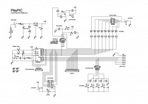
In summary, the 12F629/675 PICs represent a powerful solution for a wide range of electronics projects, particularly in the fields of robotics and remote control. Their compact size, low power requirements, and integrated features make them an excellent choice for hobbyists and professionals alike. The ability to easily program and reprogram these devices encourages experimentation and innovation, further expanding their potential applications.The 12F629/675 PICs are small 8 pin DIP devices that are ideal for our applications. They include and internal oscillator, a comparator, an analog/digital converter and timers. The Microchip PICkit1 is an ideal USB programmer. PicBasic Pro (PBP) is an easy to use package for those who have no penchant for learning the arcane language of assembler. PBP can be integrated with a free download from Mecanique called MicroCode Studio (MCS) that makes programming in PBP much easier. Microchip MPLAB is a free and superb compiler that can be downloaded from Microchip. The real treat is that MCS integrates with MPLAB and PICkit1 HI-TECH Software has release of a totally free ANSI C compiler to support selected Microchip devices.
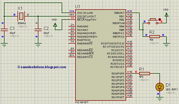
The HI-TECH PICC Lite compiler is a freeware version and supports the 16F877, 16F877A, 12F675, 12F629, 16F627, 16C84, 16F84 and 16F84A devices. This article was written to trace the steps taken by Ironsides in his quest to understand and program PICs for use in radio control applications.
CatsEyes acted as mentor. The primary interest was sparked by the use of PICs to trigger digital cameras in aerial photography. However, it soon became obvious that PICs opened up a whole Pandora`s box of possibilities for radio control in a number of applications.
Besides a single step operation such as trip a shutter, the programming of a PIC with multiple output lines offers up many possibilities, many of which derive from the extensive use of PICs in robotics. For example, an airborne PIC could be used to give a much more realistic undercarriage operation with multiple steps that are spaced in operation - using only one radio channel for to control a sequence.
So what is a PIC By one definition, it is a Turkish cloth measure, varying from 18 to 20 inches. However, for our purposes it is either a (P)eripheral (I)nterface (C)ontroller, or a (P)rogrammable (I)nterrupt (C)ontroller. Basically, it allows you to write a computer program that can then be programmed onto this tiny chip.
The chip, when powered by about 5 volts DC and connected to your airborne camera, will happily run the program using practically no electricity and execute commands you issue from your transmitter. A PIC is preferable to a servo in that the PIC weighs next to nothing ( it is about the size of a finger nail) and reacts much quicker than a servo.
It is so small that in many cases it can be housed with the body of the camera. Note: In this article the type of PIC being discussed is the newer FLASH type. The older chips were "burned" by a programmer and required ultraviolet radiation to erase them. The newer flash types can be electrically erased and reprogrammed over and over. Great for hobby experimentation where mistakes are part of the learning curve. The beauty of the PIC we will use is its ability to decode the transmitted signal. The servo pulse occurs once every 20 milliseconds. The pulse itself varies in duration from approx. 1. 0 milliseconds to 2. 0 milliseconds, and it is this variation that contains the information youwant to extract. With the stick at one extreme, the pulse for that channel would be 1. 0 milliseconds long, for a centered stick, the pulse is 1. 5 milliseconds long, and for the stick at the otherend, the pulse is 2. 0 milliseconds long. (All these are approximate and will vary with equipment used etc. ) Note: A millisecond is 1 one thousandth of a second. So to "decode" the signal, you just have to time its duration. There are several ways to do this, but perhaps the easiest is to use one of the built-in timers within a PIC such as the 12F629 or 12F675. Start thePIC timer at the start of the pulse (when the input pin goes high). At the end of the pulse (when the input pin goes back low), stop the PIC timer and read its value. The valueyou get from the timer will tell you how long the pulse was, and consequently the position of the stick on that channel.
In real 🔗 External reference
Related Circuits
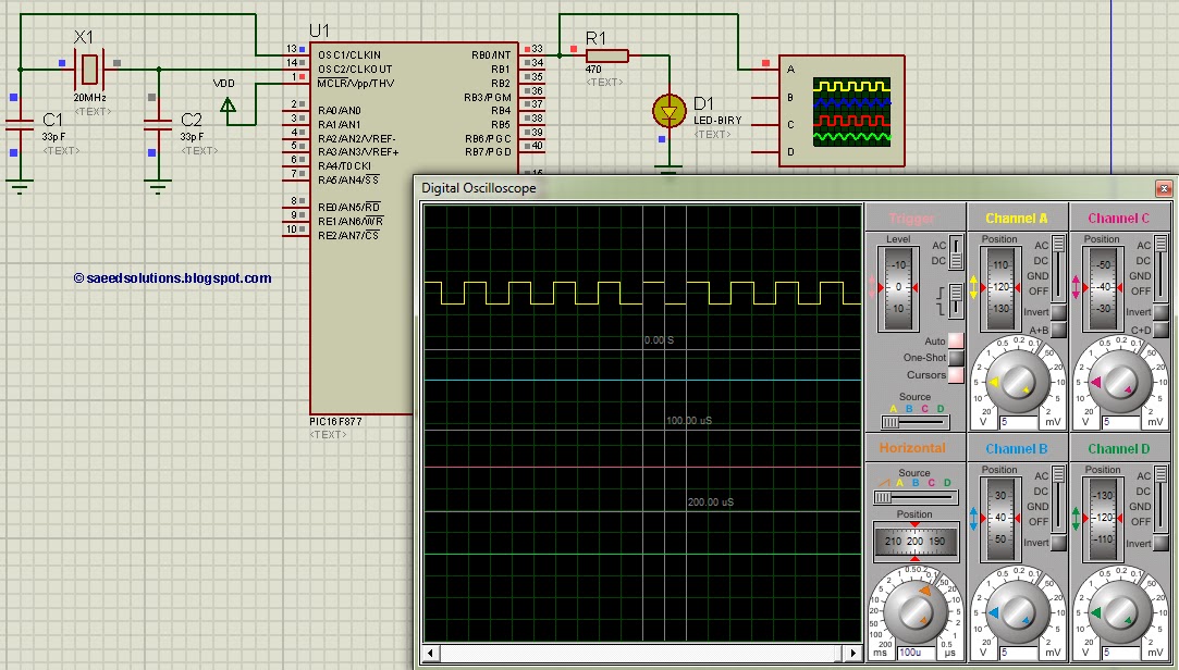
This tutorial on the PIC16F877 microcontroller addresses the question of how to utilize Timer0 and manage its interrupts. It utilizes the PIC16 simulator for demonstration purposes. The PIC16F877 microcontroller is a versatile device widely used in embedded systems. Timer0 is...
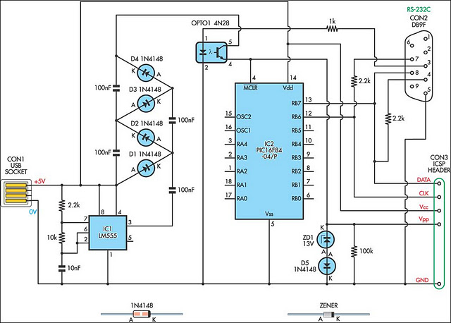
A small biped walker constructed from 2mm plywood, powered by two RC servos. It utilizes the widely available and programmable flash microcontroller PIC16F84. This simple circuit is designed to program the PIC16F84 and similar flash memory components. The project...
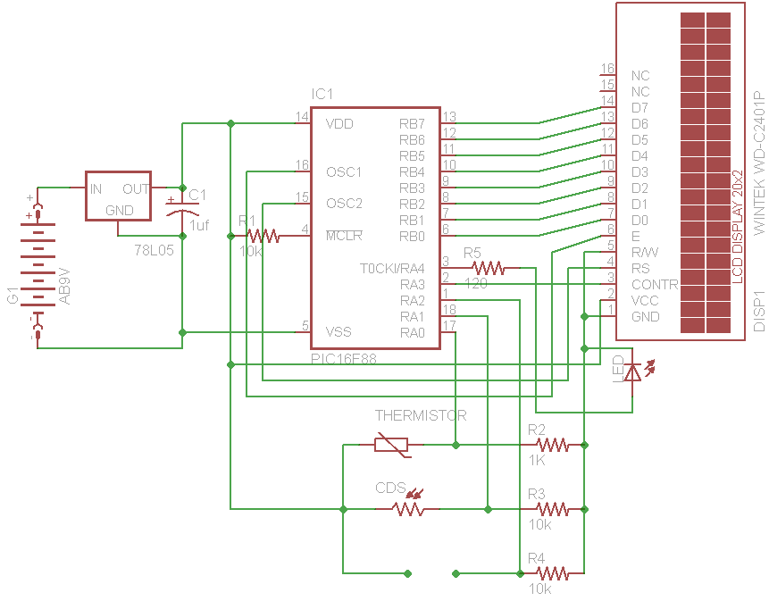
The initial concept for this project involves interfacing the WINTEK WD-C2401P LCD panel with a PIC microcontroller. The intention is to incorporate several ADC readings to provide useful information on the LCD. PORTB on the PIC serves as the...
The new design of a tutorial board based on the popular PIC16F84A microcontroller features eight single LEDs, an LCD display, and five push buttons. The tutorial board designed around the PIC16F84A microcontroller serves as a versatile platform for educational purposes...
Creating projects that connect to the phone line can be a real chore without some device like this. It generates the 48 volts DC for the on-hook condition, the 100 volts AC for the ring signal, and the 20...
This post addresses the question, "How to capture a pulse to generate an interrupt in PIC16F877?" Additionally, the PIC16 simulator (Proteus) can be utilized for verification. To capture a pulse and generate an interrupt in the PIC16F877 microcontroller, the configuration...