
pic16f877 external interrupt code and proteus simulation
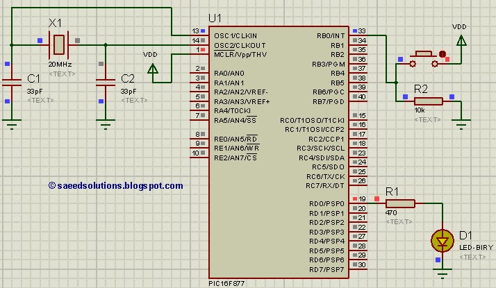
To capture a pulse and generate an interrupt in the PIC16F877 microcontroller, the configuration of the External Interrupt feature is essential. The PIC16F877 has an external interrupt pin (INT) that can be triggered by a change in voltage level, such as a rising or falling edge of a pulse.
The initial step involves setting up the appropriate registers. The INTCON register must be configured to enable the external interrupt. Specifically, the INT0IE (External Interrupt Enable) bit should be set to enable the interrupt. Additionally, the INTCON register's GIE (Global Interrupt Enable) bit must be set to allow global interrupts.
The edge-triggering configuration can be controlled through the OPTION_REG register. The INTEDG (Interrupt Edge Select) bit determines whether the interrupt is triggered on a rising edge or a falling edge. Setting this bit to '1' enables the interrupt on the rising edge, while setting it to '0' enables it on the falling edge.
Once the hardware setup is complete, the microcontroller will respond to the pulse by executing the interrupt service routine (ISR) defined in the program. The ISR should be written to handle the specific actions required when the interrupt occurs, such as toggling an LED or reading a sensor value.
For verification, the PIC16 simulator (Proteus) can be employed. By simulating the circuit, the pulse can be generated, and the behavior of the microcontroller can be observed in response to the interrupt. This allows for effective testing and debugging of the implemented logic before deploying the hardware.
In summary, capturing a pulse to generate an interrupt in the PIC16F877 involves configuring the external interrupt settings, defining the ISR, and utilizing simulation tools like Proteus for verification. This approach ensures that the microcontroller can effectively respond to external events in real-time applications.This post answers the question, ""How to capture a pulse to generate an interrupt in PIC16F877"" ? Also, using PIC16 simulator (Proteus) you can verify this.. 🔗 External reference
Related Circuits
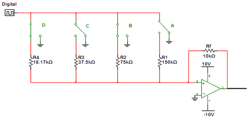
Encoders and decoders are circuits that convert analog signals to digital signals and digital signals to analog signals. The input is in digital form, while the output is a continuous sine wave or analog wave. Encoders and decoders play a...
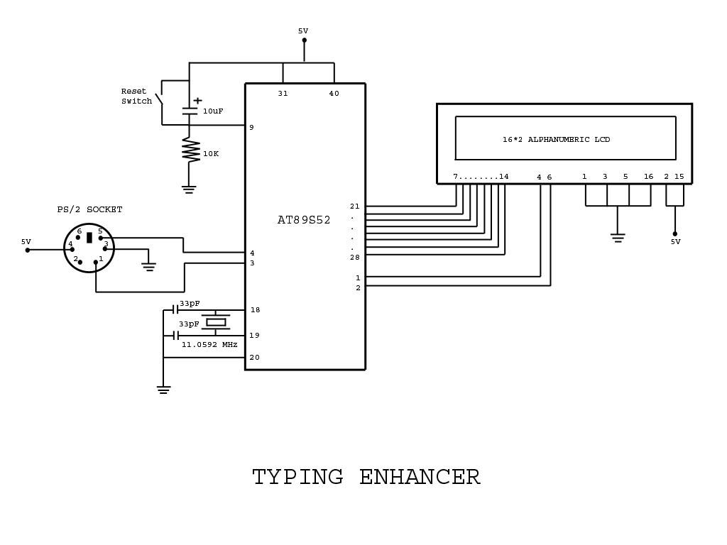
Project with Circuit and Code for a Typing Assistant using the 8051 microcontroller (AT89S52) and the PS/2 keyboard port of a computer. The project also explains the interfacing of the PS/2 port of a computer with the 8051 microcontroller. The...
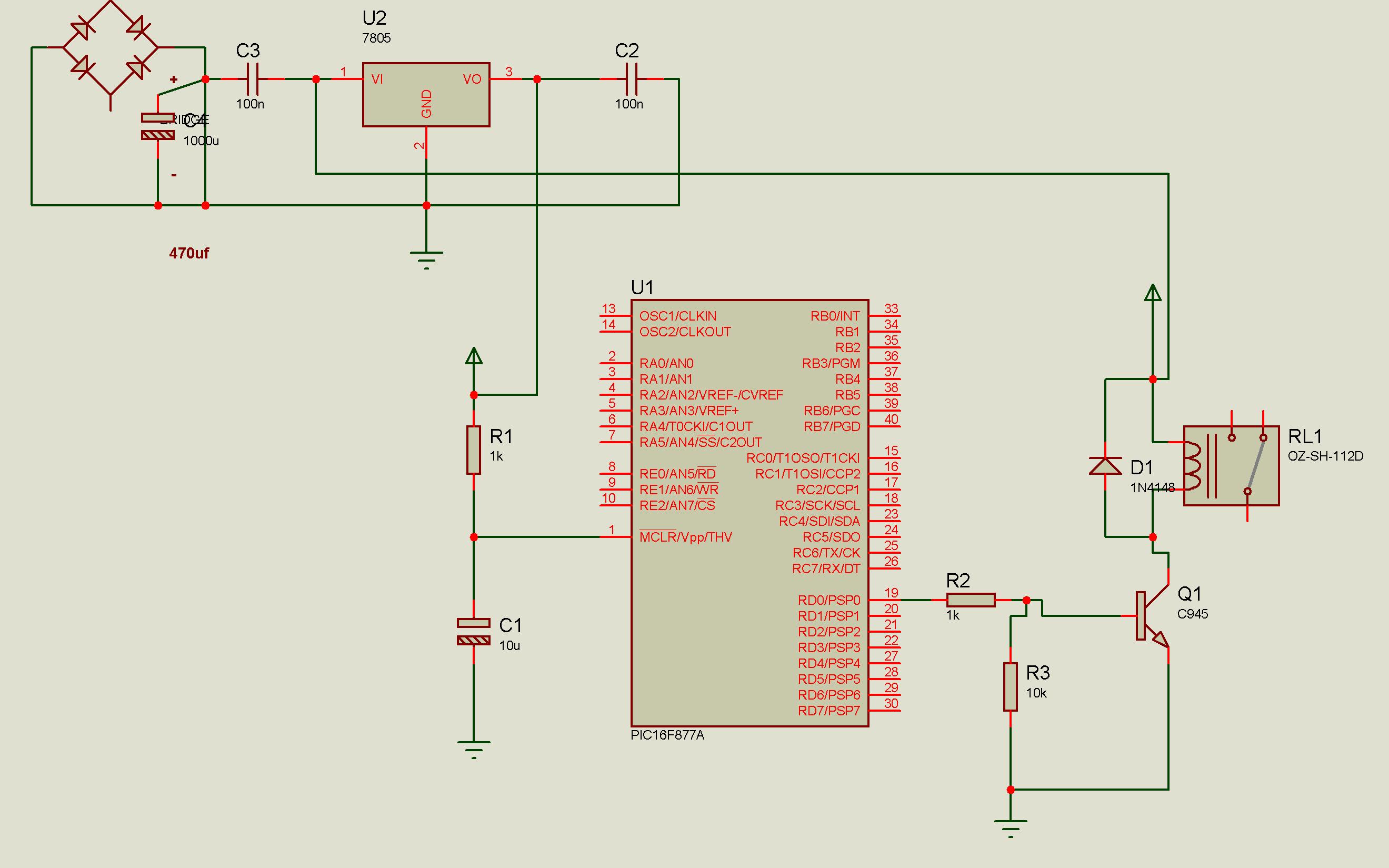
Connect a relay with a PIC microcontroller, and whenever a load is applied to the relay contacts, the PIC16F877A resets. This issue has been partially resolved by triggering another relay from the basic relay attached to the PIC, but...
The phone system used to be operated by a human operator in a telephone exchange room. The caller would pick up the phone and give instructions to the operator to connect their line to the destination on the other...
Security is a prime concern in our day-to-day life. Everyone wants to be as much secure as possible. An access control for doors forms a vital link in a security chain. The microcontroller based digital lock for Doors is...

This 200 MHz JFET cascode circuit exhibits low cross-modulation, significant signal handling capability, no need for neutralization, and automatic gain control (AGC) managed by adjusting the bias of the upper cascode JFET. A specific requirement for this circuit is...