
PIC USB Interface
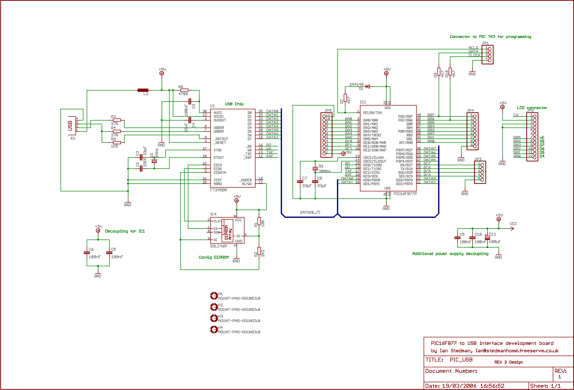
The described system operates as a simple serial communication interface between a microcontroller-based board and a personal computer. The program running on the microcontroller is designed to transmit a basic text message, "Hello world," to the PC, demonstrating fundamental serial communication principles.
The Virtual COM Port driver facilitates this communication by emulating a traditional serial port over USB. When the PCB is connected to the PC, the operating system recognizes the device and assigns it a COM port number, typically COM3: in this case, although this may differ based on the system's configuration and available ports.
To establish communication, the user must configure a terminal emulator, such as PuTTY or Hyperterminal, to match the serial settings of the microcontroller. The specified parameters—9600 BPS Baud rate, 8 data bits, no parity, and 1 stop bit—are standard for many serial communication applications, ensuring compatibility and reliable data transmission.
It is essential that the USB board is correctly configured to support these settings. This may involve setting the appropriate registers in the microcontroller firmware to enable the UART (Universal Asynchronous Receiver-Transmitter) module, which handles the serial communication. Proper initialization of the UART is critical for successful data transmission and reception.
In summary, this setup provides a straightforward method for sending data from a microcontroller to a PC, suitable for debugging and testing applications where simple text output is required. This basic example serves as a foundation for more complex serial communication tasks that can be developed as needed.The second program just sends "Hello world" to the PC. By default my board uses the Virtual COM Port (VCP) driver so you can view the output using Hyperterminal or similar program, I recommend PuTTY. The setup is quite simple, when I plug the PCB into my PC, it installs as COM3: (it will be different on your PC).
In the terminal program you select a Baud rate of 9600 BPS, 8 bits, no parity and 1 stop bit (standard settings) and connect using COM3: easy! This assumes your USB board is configured like this. 🔗 External reference
Related Circuits
This PIC software integrates frequency counter and frequency locking functions. By incorporating a couple of transistors and an operational amplifier (TL082), it is feasible to stabilize the LC oscillator frequency. The frequency reference is established from the measured frequency...
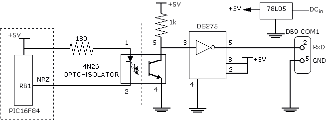
Another method that helps program development besides a dot LED as the output device is a serial bit. With a serial transmission to a terminal emulator program, developer may then test program running easier than a dot LED. One...
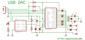
There is a significant interest in audio DAC design, particularly in creating a low-cost yet powerful audio DAC. This guide will provide instructions on how to build a personal audio DAC using the PCM2902 circuit. The project involves designing...
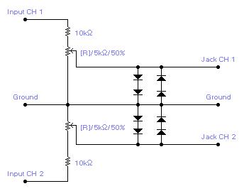
For simple electronic circuits, it may be sufficient to gain qualitative insights on dedicated electrical signals. This interface circuitry allows the line-in input of a standard PC sound card to be utilized as a 2-channel oscilloscope. Although this setup...
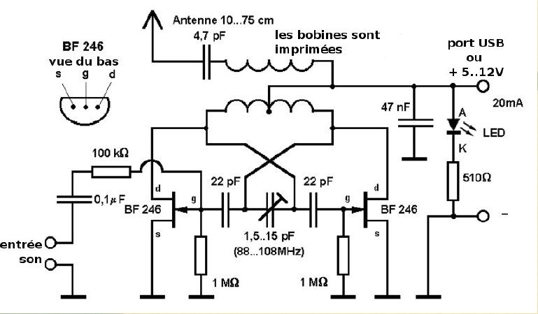
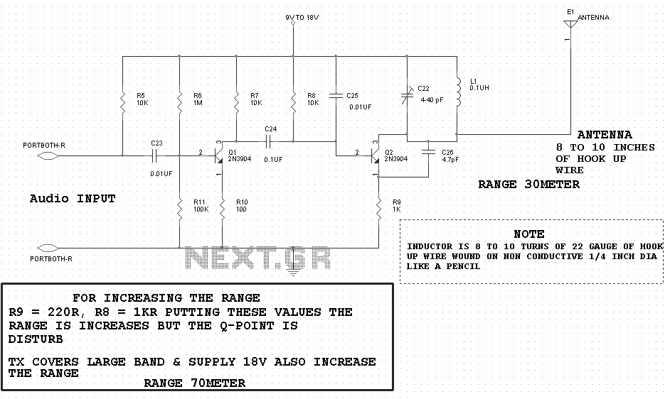
Here is a small FM transmitter circuit designed for desktop or laptop use, allowing users to enjoy movies and music from a distance. This USB-powered FM transmitter connects to a computer or MP3 player and broadcasts on a tape...
This design note presents a simple yet feature-rich 16-watt output, universal AC input adapter power supply for modems, hubs, or similar applications. The circuit utilizes a discontinuous mode (DCM) flyback converter topology designed around ON Semiconductor's NCP1027 monolithic current...