
USB FM Transmitter Circuit

This FM transmitter circuit utilizes a simple design, making it accessible for hobbyists and electronics enthusiasts. The core components include a USB power supply, a transistor for amplification, an LED for power indication, and a variable capacitor for frequency tuning. The circuit operates at a frequency of 108 MHz, which is within the FM band, allowing it to transmit audio signals effectively over short distances.
To assemble the circuit, the user should first prepare the USB power supply, ensuring proper voltage levels are maintained. The transistor should be connected with attention to orientation, as incorrect placement may lead to circuit failure. The LED serves as a visual indicator of power; thus, it should be installed with the correct polarity to function properly.
The audio input is achieved through a minijack connector, which is modified from a stereo to a mono configuration. This involves soldering the left (white) and right (red) channels together while isolating the ground (yellow) wire. This modification is essential for ensuring that the transmitter receives a proper audio signal for broadcasting.
Frequency tuning is accomplished using a variable capacitor, which allows for fine adjustments to the transmission frequency. Care should be taken when adjusting the capacitor, as excessive force may damage the component. A screwdriver or a thin, rigid piece of cardboard can be used to turn the capacitor gently until the desired frequency is reached.
Overall, this FM transmitter circuit offers a practical solution for wirelessly transmitting audio from digital devices, enhancing the listening experience in various environments. Proper assembly and tuning are critical for optimal performance, making it a valuable project for electronics enthusiasts.Here`s a small FM transmitter ciruit for your desktop or laptop to enjoy the movie and music from a distance. This FM transmitter, which is powered by USB, recovers output on your computer or your MP3 player to the relay on the tape FM (frequency 108 MHz).
For Assemblying this FM transmitter kit, an electronics hobbyist will have built in about 30 minutes. The transistor has a flat side, the LED a foot longer than the other is the anode (A), the other is the cathode (K). The audio cable (minijack) must be transformed from a stereo cable into a cable. Soldering together the white and red cables, leaving aside the yellow cable (mass). The frequency setting will be turning the variable capacitor gently with a screwdriver or thin cardboard but rigid.
🔗 External reference
Related Circuits
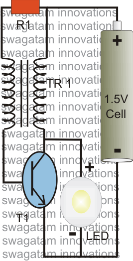
The post explains a simple 1 watt LED driver circuit using a single 1.5 V penlight cell through the joule thief concept. The coil may be wound over a T13 toroidal ferrite core using 0.2 mm or 0.3 mm...

A simple dimmer circuit can be constructed using the CMOS ICs TT8486A and TT6061A, allowing control over the intensity of an incandescent lamp through a touch contact. This electronic touch dimmer can increase the brightness of incandescent lamps in...
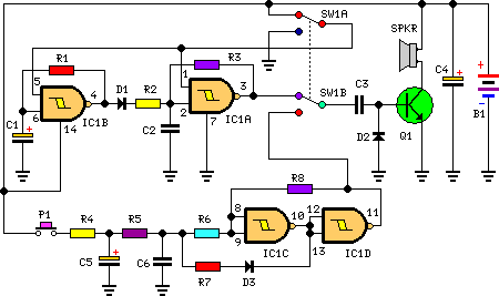
This circuit is designed for children's entertainment and can be installed on bicycles, battery-powered cars, motorcycles, as well as on models and various games and toys. When switch SW1 is positioned as depicted in the circuit diagram, it generates...
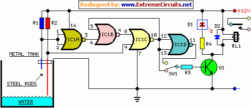
This circuit utilizes a relay to control a water pump, enabling automatic level control for a water reservoir or well. The shorter steel rod acts as the "water high" sensor, while the longer rod serves as the "water low"...

This circuit has a long history, originating from an idea by Rich Piotter and later refined by Wilf Rigter and Bruce Robinson. The final result does not include the necessary motor drivers, which are typically H-bridge based, but presents...
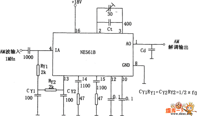
The figure illustrates a bilateral band modem circuit utilizing the NE561B component. The input modulating signal operates at a loading frequency of f0 = 1 MHz. When the AM modulation signal is applied to the input terminal of the...