
PIC16CS4 Programmer
The described PIC programmer circuit utilizes a minimalistic approach to facilitate programming of the PIC 16C84 microcontroller through the RIR02 software. The circuit employs a 74LS06 integrated circuit, which serves as a six-channel inverter, to manage data transmission between the parallel port and the microcontroller. The connection of the data lines OO, O1, and O3 to the microcontroller is crucial for effective communication, where OO is used for data input, O1 for clock signals, and O3 for programming pulses.
The circuit's design ensures that the programming process is efficient and reliable, with the inverter IC1b playing a vital role in managing the feedback from the PIC to the PC. The connection terminals K2, K3, and K4 are strategically placed to facilitate easy access to the necessary pins of the PIC, ensuring that the programming signals are correctly routed. The requirement for a 12 V programming voltage and a 5 V supply for the other components is typical in such circuits, providing the necessary power levels for operation.
In addition to the basic functionality, the inclusion of LEDs for visual feedback during programming enhances usability, allowing users to confirm that programming pulses are being applied. The protective diode D1 is an essential feature that safeguards the transistor T1 from potential damage due to high voltage spikes during programming, thus contributing to the longevity and reliability of the programmer. Overall, this schematic represents a practical solution for programming the PIC 16C84 microcontroller using the RIR02 software, combining simplicity with functionality.Most of you will certainly already installed on your computer one of the many software tools move freely from hand to hand and is suitable for programming the PIC 16C84. One of the most popular of this kind is the RIR02 of Silicon Studios. The circuit described below, is perhaps the simplest PIC programmer that can work seamlessly with the program RIR02.
This guide allows RIR02 communication with the programmer, through the parallel port (Centronics).
The components are the building are minimal and have very low costs (The most expensive of these is the connector Centronics)! The integrated 74LS06 (Inverter anoichtousyllekti sixfold) is responsible for Data exchange between the parallel port and the microcontroller to be programmed.
To this end, three of data lines of the door, the OO, O1 and O3 impose reasonable conditions on the pins of the microcontroller, but only after reverse and isolate the gates IC1c, IC1 and IC1f respectively. More specifically, the line OO provides the data to be written in component, the L1 the necessary clock pulses and O3 pulse programming.
On the other hand, the data returned by the PIC the PC, driven by the inverter IC 1 b BUSY line clamp Centronics. The complete set will be scheduled should be connected to terminals K2, K3 and K4 in the following way: The point of the K3 OATA the RB7 pin of the PIC (pin 13) pin CLOCK in the K3 RB6 pin of PIC (pin 12) Pin's K4 MCLR MCLR pin on the PIC (pin 4) The +5 V pin to pin of K2 YOO the PIC (pin 14) The GROUND pin of K2 in the VSS pin of the PIC (pin 5).
Spike + nip the K4 accepts the programming voltage of the integrated, which should have a value of 12 V. The 2 LED illuminates as applied programming pulses. The diode D 1 protects the base of the transistor T1 by the voltage programming. The programmer requires two external voltages: one of 12 V (voltage programming PIC) and one of the 5 V (Feeding the 74LS06 and LED).
🔗 External reference
Related Circuits
Atmel Flash devices are well-suited for development due to their ease and speed of reprogramming. They provide ample code space for applications, especially for projects involving the 89Cxx series with the C programming language. Atmel offers a wide selection...
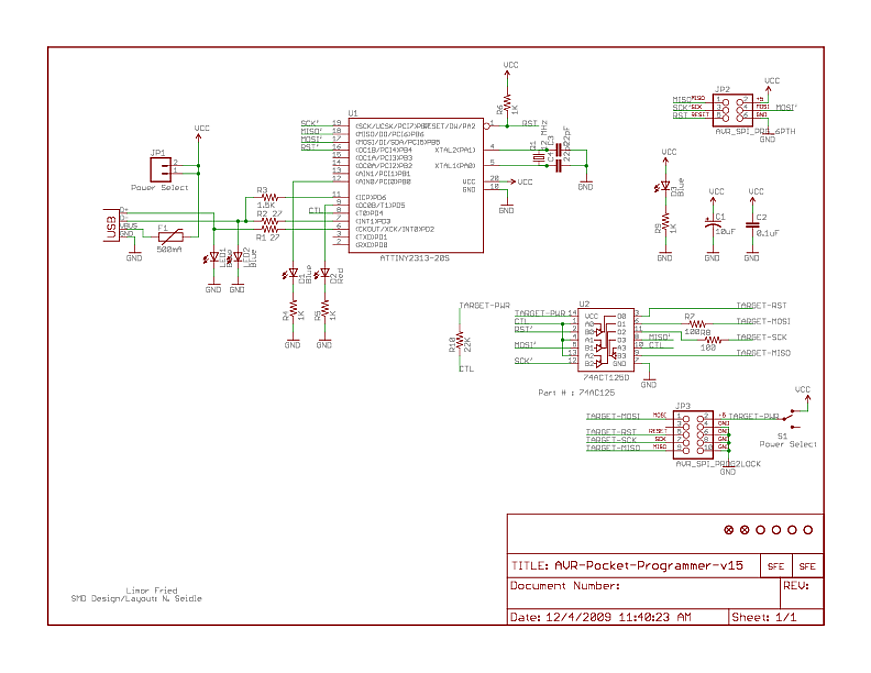
At the bottom, there is a 74AC125, which is a quad buffer with tri-state outputs. Numerous buffers of this type have been observed in programmers. The function of these buffers is not entirely clear, but it is assumed that...
C0QBmk~%24(KGrHqIOKkIEq4M%2Bu,)1BK2zHH580Q~~_35.gif)
This time, information will be shared about the schematics of radios, specifically the schematic of a programmer radio, along with the latest information available on Onmilwiki. The schematic of a programmer radio typically includes various components essential for its operation,...
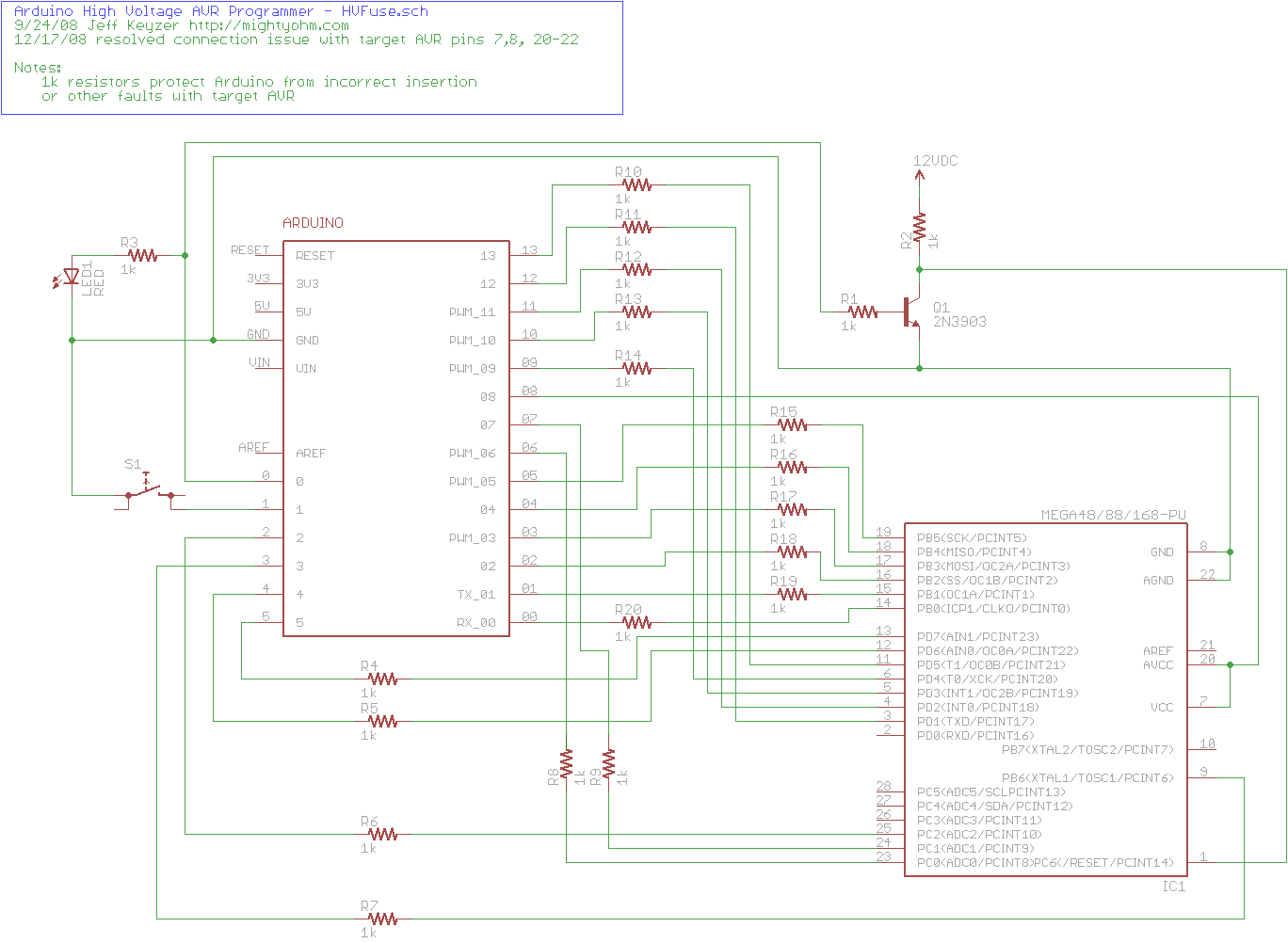
The project explains how to create a simple AVR High Voltage Programmer using Arduino. It can be utilized to fix or recover incorrectly fused AVR chips. The AVR High Voltage Programmer is designed to reprogram AVR microcontrollers that have been...
The idea behind this project is to provide some means of loading a program into a PIC that will then be able to program other PICs in a more conventional way. How do you program a PIC to be...
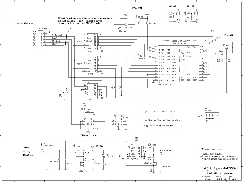
This GAL programmer is controlled via a parallel port, so that any exclusive interface is not required for the programmer. It is easy to use on the notebook PCs. When programming a PIC, a socket converter is needed. After...
Warning: include(partials/cookie-banner.php): Failed to open stream: Permission denied in /var/www/html/nextgr/view-circuit.php on line 713
Warning: include(): Failed opening 'partials/cookie-banner.php' for inclusion (include_path='.:/usr/share/php') in /var/www/html/nextgr/view-circuit.php on line 713