
ASCII Programmer PIC16F84
Next, the data bits that the PIC will store are extracted from the ASCII value. The circuit path for this is in teal.
Now the tricky part...
The IC used in the circuit is a Schmitt Trigger Quad NAND gate. U1a is configured as a monostable multivibrator. When the incoming signal goes from 0V to 5V, capacitor C1 charges via R3. This has the effect of producing a very short positive pulse at U1a pin 2. U1a pin 1 is tied to the 5 volt rail so the output of this gate, pin 3, goes low for a brief period and then it goes high again. When the output from this gate goes high, the next monostable, U1b, is triggered in the same way. The difference here is that the time period is slightly longer. The 47k resistor is greater than the 15k resistor. This produces the pulse that is used to clock the data into the PIC. Unfortunately, it is upside down at this point, so U1c is used to invert the signal which is now at the blue part of the circuit. Diodes D2 and D3 provide quick discharge paths for the capacitors. The ASCII characters that produce this data are: Null Character (#0) and DEL Character (#127).
The circuit design effectively utilizes the characteristics of the Schmitt Trigger to ensure clean transitions of the signal, which is crucial in digital circuits where noise and signal integrity can lead to programming errors. The use of a monostable multivibrator configuration allows for the generation of precise timing pulses necessary for the programming sequence of the PIC microcontroller. The choice of resistors and capacitors in the timing circuit directly affects the pulse width and frequency, which must be carefully calculated to match the specifications of the target PIC device.
The implementation of voltage clamping and level shifting through the use of resistors and diodes ensures that the incoming serial data is safely converted from the higher voltage levels of the PC serial port to the lower voltage levels required by the PIC. This is critical to prevent damage to the microcontroller during operation. The circuit's simplicity and reliance on commonly available components facilitate easy construction and troubleshooting, making it an ideal solution for hobbyists and engineers looking to program PIC devices without the need for specialized programming equipment.
In summary, this project demonstrates a cost-effective and efficient method for programming PIC microcontrollers using a basic serial connection, leveraging simple electronic components to achieve reliable functionality.The idea behind this project is to provide some means of loading a program into a PIC that will then be able to program other PICs in a more conventional way. How do you program a PIC to be a programming device without a programmer, and why would you want to build a programmer if you already have one that can program the PIC to be a programmer.
The answer here is to try to build a very cheap circuit that is easy to build and does not need any special software to do the job. That way, after it has done it's job, the parts can end up back into the junk box. The simplest approach I could come up with, was to use a simple circuit, the PC Serial Port and be able to program a PIC just by sending (2) different ASCII codes.
This way, you do not need any special software to set up, and the circuit can be built out of junk bits and pieces. This programmer is not capable of reading data from a PIC, but for the purpose it is meant for, that doesn't matter.
While programming, new data bits entering the PIC are placed on pin RB7 while the clock pulse appearing on pin RB6 is in a high state. The PIC will accept the new data when the clock line is brought low. Programming comands are 6 bits long, and the data that follows consists of a Low Start Bit plus 14 data bits that the PIC will store in memory and then a Low Stop Bit.
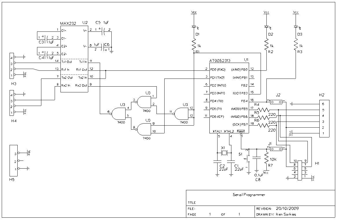
The circuit shown below extracts clock pulses and data bits from the data stream produced by sending the (2) ASCII codes from the serial port. The circuit is very simple and is also easy to construct. ASCII data comes on the Tx line from the PC serial port on Pin 3 of a DB9 connector. This data is shown in MAGENTA and can be around 11 volts above and below ground. This is damaging to a circuit that is designed to run on 5 volts, so R1 and Z1 reduce the positive voltage to 5 volts and the negative voltage is blocked by D1.
Next the data bits that the PIC will store are extracted from the ASCII value. The circuit path for this is in TEAL. Now the tricky part... The IC used in the circuit is a Schmitt Trigger Quad NAND gate. U1a is configured as a monostable multivibrator. When the incoming signal goes from 0V to 5V, capacitor C1 charges via R3. This has the effect of producing a very short +ve pulse at U1a pin 2. U1a pin 1 is tied to the 5 volt rail so the output of this gate, pin 3, goes low for a brief period and then it goes high again. When the output from this gate goes high, the next monostable, U1b, is trigerred in the same way. The difference here is that the time period is slightly longer. The 47k resistor is greater than the 15k resistor. This produces the pulse that is used to clock the data into the PIC. Unfortunately, it is upside down at this point, so U1c is used to invert the signal which is now at the BLUE part of the circuit.
Diodes D2 and D3 provide quick discharge paths for the capacitors. The ASCII characters that produce this data are :- #0 Null Character #127 DEL Character 🔗 External reference
Related Circuits
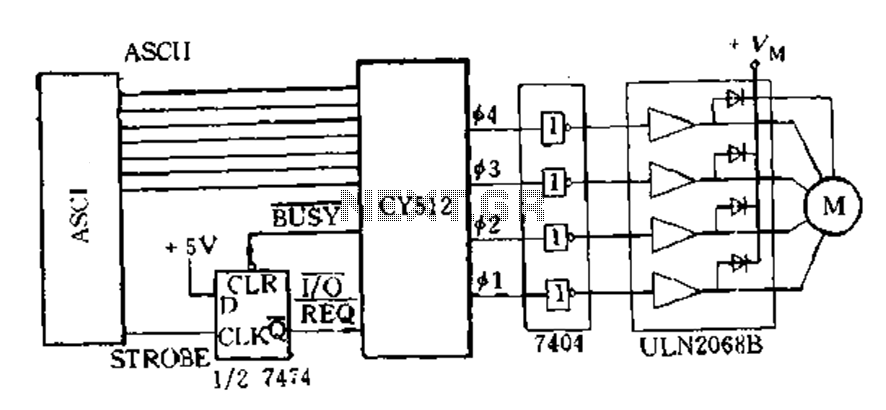
The CY512 is an easily developed system that operates using ASCII keyboard code. It features three operating modes: 1) Immediate command execution mode, where users can input ASCII commands to directly control the stepping motor movement in decimal stepping...
The image below displays the schematic diagram of the SPI Flash programmer hardware interface. Power for the interface can be supplied using either a 9V DC adapter or a 9V battery. The 74HCT367 integrated circuit (IC) buffers the adjacent...
This is a beta release schematic. Use at your own risk. The idea is to add this circuitry to a board that already has RAM at address 2000 and an 82C55 I/O chip to provide ports A, B, and...

This ISP Programmer can be utilized for in-system programming or as a standalone SPI programmer for Atmel ISP programmable devices. The programming interface is compatible with STK200 ISP programmer hardware, allowing users of STK200 to also employ the software...
Atmel's application note AVR109 describes a bootloader that utilizes the UART for communication of FLASH programming instructions. It also provides sample C code that facilitates the programming of FLASH, EEPROM, and lock bits. It is important to note that...
For the following circuit of the JDM PIC microcontroller programmer, information is needed regarding the PIC microcontroller pins that receive the RS232 signals. The JDM PIC microcontroller programmer is a widely used circuit for programming PIC microcontrollers via the RS232...
Warning: include(partials/cookie-banner.php): Failed to open stream: Permission denied in /var/www/html/nextgr/view-circuit.php on line 713
Warning: include(): Failed opening 'partials/cookie-banner.php' for inclusion (include_path='.:/usr/share/php') in /var/www/html/nextgr/view-circuit.php on line 713