
PIC16F84 IC For 40 MHZ/400 MHZ Frequency Counter

The frequency counter circuit operates within the range of 40 MHz to 400 MHz, utilizing the PIC16F84 microcontroller as its core component. The PIC16F84 is an 8-bit microcontroller from Microchip Technology, well-suited for applications requiring precise timing and counting capabilities.
In this circuit, the input signal is fed into the microcontroller through a suitable input pin. The microcontroller is programmed to count the number of signal cycles over a specified time interval, providing a digital representation of the frequency. The programming of the PIC16F84 involves configuring its timers and counters to accurately measure the input frequency.
The circuit typically includes additional components such as resistors, capacitors, and possibly a crystal oscillator to stabilize the timing functions of the microcontroller. The output of the frequency count can be displayed on a digital readout, such as a 7-segment display or an LCD, depending on the design requirements.
Power supply considerations are also important; the circuit may require a regulated voltage supply to ensure stable operation of the PIC16F84 and other components. Proper grounding and layout techniques should be employed to minimize noise and interference, which could affect the accuracy of frequency measurements.
Overall, this frequency counter circuit represents a practical application of microcontroller technology in measuring high-frequency signals, suitable for use in various electronic testing and measurement scenarios.The following circuit shows about 40 MHZ/400 MHZ Frequency Counter Circuit Diagram. This circuit based on the PIC16F84 IC. Features: with .. 🔗 External reference
Related Circuits
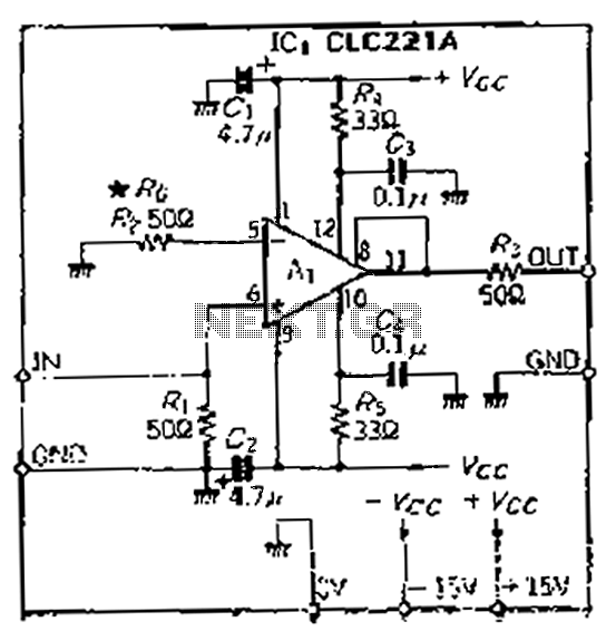
The CLC221A is designed with a traditional operational amplifier (OP) configuration. It is a high-performance current-feedback amplifier capable of operating in both non-inverting and inverting modes. The amplifier features a flat-rate characteristic, which is particularly effective when configured in...
This circuit utilizes the versatile MAX038 function generator. While some advanced features of this IC are disabled in this configuration, it is capable of generating sine, triangle, and square waves by adjusting the A0 and A1 pins (refer to...
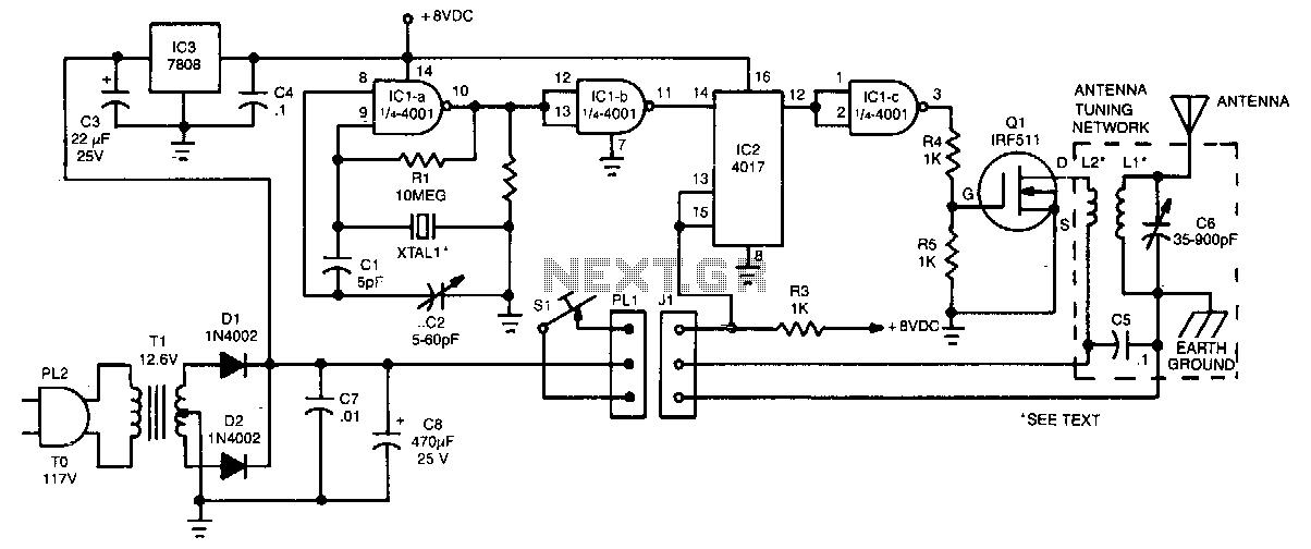
The crystal oscillator utilizes two sections of IC1, a 4001 quad 2-input NOR gate, representing a standard and reliable design. The oscillator generates a 1.85-MHz square-wave output that feeds into IC2, a 4017 divide-by-10 counter. The count enable and...
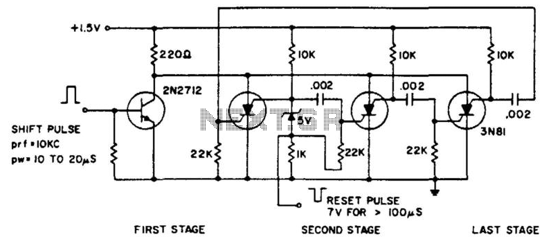
The ring counter operates from 1.0 to 6.0 V and requires only 6 mW at 1.5 V. The reset pulse activates the first stage with its trailing edge. The maximum shift pulse width increases with voltage and approaches 70...
The 4017 traffic light circuit connects four legs to the green LED and two legs to the amber LED. This configuration raises the question of whether it could function with only one leg per LED. Each output is activated...
To achieve greater sensitivity, consider using the 74AC04 or 74HC04 in place of the 74HCU04 for component U1. While the 74AC04 and 74HC04 may offer improved performance over the 74HCU04, it is important to note that the frequency response...