
controller 4017 counter LEDs have multiple connections in this traffic light circuit
The 4017 decade counter is widely utilized in timing and sequencing applications, such as traffic light control systems. In this circuit, the green LED is connected to outputs Q0, Q1, Q2, and Q3, allowing it to remain on for a cumulative duration of four time units. This is achieved through a wired-OR connection, which effectively combines multiple outputs into a single active state. The result is an extended illumination period for the green LED, which is essential for traffic management.
The amber LED is connected to outputs Q4 and Q5, indicating a transitional state between green and red. This setup ensures that the amber light activates for a shorter duration, signaling drivers to prepare to stop. The use of two legs for the amber LED allows for a more reliable, brighter signal compared to a single connection.
The carry output, denoted as ":10", serves a critical role in the operation of the red LED. By linking the outputs Q0 through Q4, the circuit can effectively manage the timing of the red light, ensuring it remains illuminated for the necessary duration to allow vehicles to stop safely. The design of the circuit is carefully calibrated to reflect standard traffic light sequences, enhancing road safety and efficiency.
In summary, the 4017 traffic light circuit employs a strategic connection of multiple outputs to control the LEDs, utilizing both wired-OR configurations and carry outputs to optimize the timing and visibility of the traffic signals. This design not only meets functional requirements but also adheres to established traffic management protocols.Why are four legs connected to the green LED and two to the amber LED in the 4017 traffic light circuit Shouldn`t it be able to do with only one leg per LED Each output is consecutively active for the same time. By wired-OR-ing outputs you can create longer active times. So the green LED will be on during 4 time units. Normally you would have to wired-OR Q0 through Q4 for the red LED, but we have a carry output (here called ":10") which does just that, see the bottom trace of the timing diagram: 🔗 External reference
Related Circuits
Design a circuit using a power MOSFET to replace the NTC thermistor that many Mag623 users employ to prevent their bulbs from flashing. Although inexpensive and easy to connect, NTCs run quite hot, are affected by ambient temperature, require...
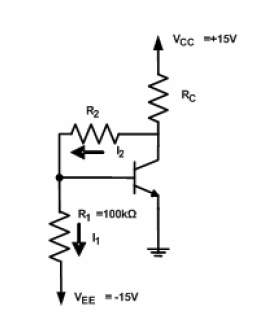
A circuit diagram has been provided for analysis, with the objective of calculating the values of resistors R2 and RC. The circuit is designed to operate at the Q-point with the following parameters: VCE = 5V, VBE = 0.7V,...
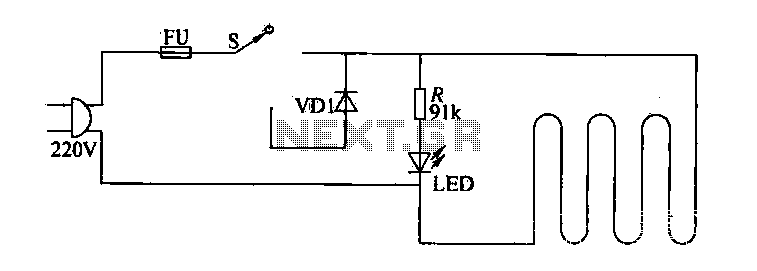
The circuit of electric blankets is controlled by switch S. When switch S is fully engaged, the entire supply voltage of 220V is applied to the heating wire, resulting in a high-temperature state. When a lower temperature is desired,...
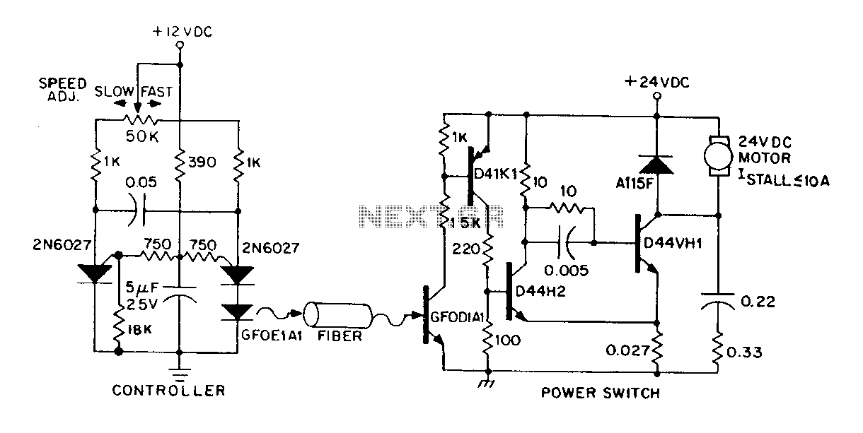
A DC power supply can be controlled through an optical fiber. The circuit includes a small DC motor (1/12 hp) that offers an isolated speed control channel. The control logic operates as an independent module, consuming 300 mW of...
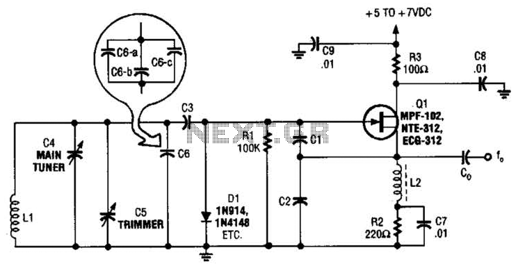
This basic VFO (Voltage Controlled Oscillator) operates within the 3 to 6 MHz frequency range and is commonly utilized in amateur radio applications, employing a Colpitts oscillator configuration. For operation at frequencies between 5 to 5.5 MHz, capacitors C2...
Figure 7-2 illustrates the FSK (Frequency Shift Keying) signal demodulation circuit, which is built using a digital phase-locked loop. This circuit features two oscillators operating at distinct frequencies: crystal oscillator X with a frequency of 983.04 kHz and crystal...